ACTIVITY-ON-NODE Critical Path Diagram
What It Is
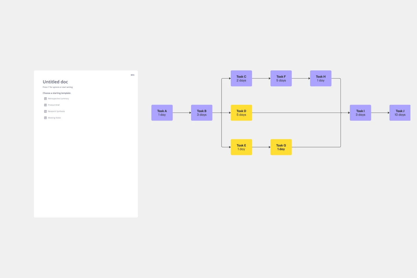
A PERT Network Diagram built on the Activity-on-Node (AON) method, designed for project schedule analysis and critical path identification. This template provides a visual framework for mapping task dependencies and calculating which activities directly control your project's end date.
What It's Used For
Use this template to map every project task as a node and every dependency as a directional arrow. By performing forward and backward passes, you'll calculate the critical path and surface zero-slack tasks—the activities that cannot be delayed without pushing out your project deadline. This visibility helps project managers prioritize resources, anticipate bottlenecks, and communicate schedule risks to stakeholders.
Key Components
START Node
A green pill-shaped node anchoring the left side of the network, marking the project's beginning.
Task Nodes (A through H)
Eight placeholder nodes arranged in a branching left-to-right network. Each contains:
Visual Styles
Two distinct node formats help you instantly identify schedule constraints:
Dependency Arrows
Directional connectors showing task sequence—styled in green for critical path segments and dark for non-critical flows.
Node Anatomy Legend
An upper-left reference explaining each field inside a node.
Summary Banner
A bottom section capturing the critical path chain, total project duration in working days, earliest finish date, and a watch list prompt for near-critical tasks.
How to Use It
Customize nodes — Rename each task and enter its duration
Map dependencies — Redraw arrows to reflect real project relationships; add or delete nodes as needed
Forward pass (left to right) — ES = latest EF of all predecessors; EF = ES + Duration
Backward pass (right to left) — LF = earliest LS of all successors; LS = LF − Duration
Identify critical path — Calculate Slack = LS − ES for each task; recolour any zero-slack node with the green critical style
Key Formulas
Cheers!
Khawaja Rizwan