Key steps, best practices, templates, and tools to create an AWS network diagram
Summary
In this guide, you will learn:
- How to define AWS network diagram requirements based on business goals
- How to use Miro’s diagramming tools to create and collaborate on AWS network diagrams efficiently
- Best practices for effective AWS network diagrams, such as starting with VPCs and subnets and using standardized AWS icons
- The advantages of combining automated AWS diagram generation tools with manual editors like Miro for customization and sharing
- How Miro’s AWS architecture diagram tool supports real-time and asynchronous collaboration
- Step-by-step instructions for customizing AWS architecture diagrams in Miro using drag-and-drop AWS icons and templates
Any unexpected changes in the network that connect various parts of your Amazon Web Services (AWS) cloud environment with the internet can seriously impact performance. Connectivity issues might slow down your apps or even cause crashes, which isn’t great for your users—or your business in the long run.
This is where AWS network diagrams come in handy. They show how your AWS services and resources are interconnected, highlighting the key components that keep your network running. If something goes wrong, you can compare a historical snapshot of your network with the live version to quickly pinpoint and fix issues.
To create an AWS network diagram accurately, you must understand its key components and their relationships. In this guide, we’ll explain how each component works, provide concrete steps for designing a network diagram, and offer examples and handy tools to streamline the process.
AWS cloud architecture
Drag and drop AWS shapes, save time with AWS templates, and easily build technical diagrams.
What is an AWS network diagram?
A network diagram visualizes a system’s network activity—a flow of incoming data (i.e., a user visiting your website) and outgoing data (i.e.. responses your website sends to the user). It uses symbols and icons to represent different network components, allowing you to understand how your network is structured and how its elements work.
AWS network topology diagrams illustrate an AWS network architecture in particular, focusing on specific components like VPCs and subnets rather than general network elements like servers and routers.
Besides visualizing your entire AWS cloud network, these diagrams can help you:
- Spot potential roadblocks and remove them on time
- Identify areas for improvement
- Share the network outline to keep all teams on the same page
Network admins, system architects, and IT professionals typically use network topology diagrams to optimize the design, management, and troubleshooting processes of computer and telecom networks. Project managers also use network diagrams to outline project activities and identify task dependencies.
Key components of an AWS network diagram
A well-structured AWS network diagram shows traffic flows to and from the internet. It also illustrates connections between key components like virtual private clouds, subnets, and internet gateways.
In the following sections, we’ll explain how these key elements work and interact with each other.
VPC (Virtual Private Cloud)
Virtual Private Cloud (VPC) is an isolated virtual network hosted within a public cloud. Think of a VPC as a reserved table in a crowded restaurant—only the group who made the reservation can access it.
A VPC allows you to store data, host websites, run code, and perform other operations you would typically carry out in a public cloud. However, it does so in an isolated section where your data is protected, and access is restricted to authorized users.
An AWS VPC may resemble a traditional data center or office network. However, it provides a scalable infrastructure, meaning you can adjust the resources you use and only pay for services necessary for critical business operations.
As a private, secure network entailing all your cloud resources, VPC is the foundation of an AWS network architecture diagram. Once you create a VPC, you can add other key components that make up a network diagram, like subnets and routing tables.
Subnets
Subnets are smaller networks or groups of IP addresses—unique numbers identifying your device in a network—within your VPC. You can set up AWS resources like EC2 instances (virtual servers) in specific subnets for improved organization and easier access control.
We can compare IP addresses to street addresses and subnets to neighborhoods in a city. Like a neighborhood is located in one part of the city, a subnet resides within one Availability Zone (AZ). AZs are isolated data centers in a certain Region, such as the US, Europe, or China.
To protect your application’s network architecture from failures, you can launch AWS resources like EC2 instances from subnets in separate AZs. This way, if one AZ fails due to network disruptions, others can handle incoming user requests.
There are several types of subnets you can create, including the two main types:
- Public subnets: They have a direct route to the internet, meaning the resources you hold in a public subnet can access the public web.
- Private subnets: They don’t have a direct route to an internet gateway, meaning your resources need a NAT device, typically a router or a firewall, to access the public internet.
You’d create public subnets in your AWS network topology diagram for resources like web servers designed for user interaction. On the other hand, you’d add private subnets for resources you want to protect from unauthorized access, like databases.
Internet gateway
An internet gateway enables communication between your VPC and the internet. It lets your resources, like EC2 instances, connect to the internet if they have a public IPv4 or IPv6 address. These addresses are connectionless protocols that break data into smaller blocks for more efficient transmission across the internet. Internet gateways also allow instances on the internet to connect to resources in your subnets.
NAT gateway
A Network Address Translation (NAT) gateway allows instances in private subnets to connect to services outside a VPC. Since external services can't directly connect to resources in private subnets, a NAT gateway translates the instances’ private IP addresses to a public IP address, preventing exposure to unsolicited inbound connections.
NAT gateway works similarly to your home internet router. Devices like phones and computers connect to the router to access the internet. The router uses a public IP address to connect to the internet, but it assigns the devices a private IP address to keep them safe.
When you create a NAT gateway, you need to choose between two connectivity types:
- Public (Default): Connects instances in private subnets to the internet but prevents inbound connections. For example, when you need to download updates, your server sends a request to the internet through a public gateway.
- Private: Allows instances in private subnets to connect to your on-premises network or other VPCs. For example, when your private database needs to communicate with your company’s data center, a private NAT gateway enables secure communication without exposing data to the public internet.
Route tables
Route tables direct network traffic by using specific rules, similar to maps, to determine the best paths for data to travel.
Every VPC has a default main route table that only contains a local route for communication within the network. However, you can modify the main route table or add more specific routes, like NAT or internet gateways, to direct traffic as needed.
You can assign a route table to a specific subnet; if you don’t, the subnet will automatically use the main route table. You might also associate multiple subnets with a single subnet route table.
Security groups and network access control lists
Security groups control the traffic that can leave or reach resources like EC2 instances. Every VPC has a default security group, but you can create additional ones with specific rules on which traffic can reach or leave your VPC resources.
Network access control lists (NACLs) work similarly, but they control inbound and outbound traffic for your subnets.
Both security groups and NACLs follow specific rules for allowing and denying traffic flow to and from your VPC, but they differ in the following aspects:
Aspect | Security Groups | NACLs |
Scope | Operate at the instance level. | Operate at the subnet level. |
State | They’re stateful, meaning they allow outgoing traffic automatically if you allow incoming traffic. | They’re stateless, meaning you have to allow outgoing traffic manually. |
Rule Type | They let you create rules for allowed traffic but don’t let you deny IP addresses from connecting to your instances. | They let you allow and deny connections with certain IP addresses. |
Rule Process Order | They evaluate all rules before deciding if they should allow traffic. | They evaluate rules in a numbered order, starting with the lowest. |
Occurrence | There can be multiple security groups for one instance. | There can be only one NACL per subnet. |
How to create an AWS network diagram in 5 steps
In the following section, we’ll provide a step-by-step guide on creating an AWS network diagram.
Step 1. Define your requirements
Before creating an AWS network topology diagram, determine its purpose based on your business goals.
For example, if you’re planning to present a high-level overview of your operation’s network to your stakeholders, you should create an AWS network diagram that focuses on the main components like VPCs and subnets.
Meanwhile, if you’re creating a network diagram for troubleshooting, it should include more detailed elements, focusing on routing and internet flow through gateways. This can help you spot network issues quickly and determine why your network is slow or down.
Step 2. Choose a diagramming tool
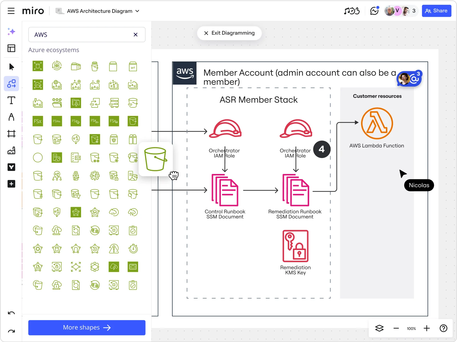
Once you define your requirements and goals, you should choose the right tools for creating AWS network diagrams. For example, Miro is an Innovation Workspace that offers various tools, features, and templates to help you build a network diagram together with your team.
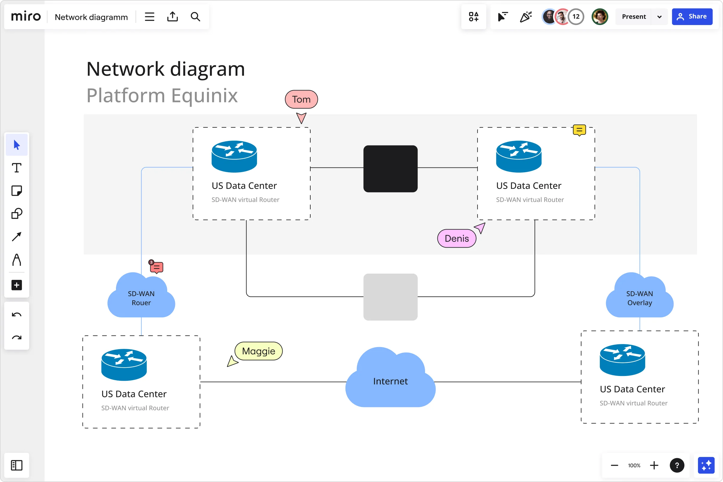
Miro’s network diagram tool lets you map out the topology of your AWS network with a few clicks. It provides access to unique shapes and symbols representing AWS network components and services. You can add those shapes to Miro’s infinite canvas to build your diagram and share it with the whole team.
Speed up the diagram design process with network diagram templates. Choose some of the 29+ ready-made options and tailor them to your liking using drag-and-drop shapes, lines, and icons. You can also invite team members to communicate their ideas in real time or async.
Step 3. Start with the VPC and subnets
Since VPC is the basic building block of an AWS network diagram, you can use a diagramming tool to draw a large box that represents the VPC.
Before adding other components, specify an IP address range your resources will use to communicate inside the VPC. You can do this using a CIDR block—a set of IP addresses sharing the same network prefix and number of bits. IPv4 CIDR blocks are necessary, while IPv6 CIDR blocks are optional, and you typically use them if your application supports modern systems.
Draw smaller boxes inside the VPC box to represent public and private subnets. Name them to indicate which one is private and which is public and add their IP address range. Specify which Availability Zone each subnet is located in.
Step 4. Configure route tables and add gateways and endpoints
Add boxes outside subnets to represent their routing tables and use arrows to connect each subnet to its routing table. Then set rules for each route table to indicate where they should direct traffic.
For example, arrows let you specify that the public subnet’s route table should direct traffic to an internet gateway, and a private subnet’s route table should direct traffic to a NAT gateway.
If you want to provide your resources, like EC2 instances, direct access to a service like Simple Storage Service (S3) or DynamoDB—a serverless cloud database—you can use VPC endpoints. Instead of routing traffic to an internet or NAT gateway, you can create an endpoint for S3 or DynamoDB to allow your EC2 instance private access to a storage or database without public internet.
Step 5. Implement security groups and NACLs
Add icons or notes next to resources with which you'll associate a security group or NCAL. For each resource, you should set rules for incoming and outgoing traffic that security groups and NCALs will follow. Make sure you specify:
- Type of traffic: For example, you can specify that only Secure Shell (SSH) traffic that provides secure access between a local and remote computer can reach your instances.
- Protocol: You can specify any protocol with a standard protocol number, like the Internet Control Message Protocol (ICMP) used for communicating data transmission errors.
- Source: Set rules to indicate a location from which traffic is allowed to reach your resources (for example, from a specific private network or anywhere from the internet).
- Destination: Specify where on the internet you allow outgoing traffic to go. For example, you can only allow traffic to private subnets.
How Miro can help you draw an AWS network diagram
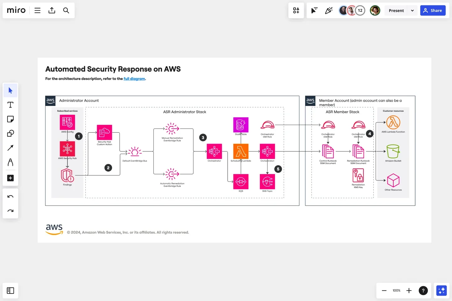
Miro simplifies the process of creating AWS network and other diagrams with its powerful AWS architecture diagram capabilities. Its intelligent canvas lets you:
- Use shapes for AWS network services and resources like VPCs and subnets to start your diagram effortlessly.
- Leverage arrows to illustrate the flow of information between subnets and gateways.
Include icons to specify which resources are associated with which security group or NCAL.
Miro has an entire suite of solutions designed to streamline your AWS diagramming experience. Its most notable tools and features include:
- AWS Cloud View app: It allows you to automatically generate an AWS network diagram based on the data you import directly from your AWS account.
- Diagram Focus Mode: Personalize AWS network diagrams to meet your project requirements, use layers to create multi-dimensional diagrams, and update alignment and distribution effortlessly.
- Real-time and async collaboration: Collaborate on the design of your AWS network diagram within a single platform. Rely on features like async Talktracks, interactive presentations, and live workshops to keep everyone in the loop and stay aligned with your business goals.
- Security and Compliance: Leverage options like user access controls and normalized audit logs to keep your AWS network diagram secure.
- AWS Cost Calculator: Estimate the cost of your AWS resources directly on your Miro board to avoid overpaying for services you rarely use.
Miro also offers 13+ AWS diagram templates to assist you in designing scalable solutions, mapping out cloud architecture, or planning robust infrastructure without drawing diagrams from scratch.
How businesses use Miro to improve AWS cloud architecture
ClickHouse—a database management system company—turned to Miro when it faced challenges creating cloud architecture diagrams. Its engineers struggled with scattered information, time-consuming diagramming, and maintaining alignment across tools and time zones.
Author: Miro Team
Last update: October 7, 2025