Table of contents
Table of contents
How to create a circuit diagram in Miro
Summary
In this article, you'll learn:
- A circuit diagram uses standardized symbols to show how components in an electrical circuit are connected and how current flows through them.
- Common circuit diagram symbols include resistors, capacitors, diodes, LEDs, transistors, logic gates, and power sources.
- Series circuit diagrams connect components in a single loop; parallel circuit diagrams connect components across shared nodes so each branch operates independently.
- Miro has 79 electrical engineering shapes for building professional circuit diagrams directly on a shared canvas.
- Teams can collaborate on circuit diagrams in real time or asynchronously, with comments, voting, and sticky notes built in — no separate review meeting required.
- Finished diagrams can be exported as PDFs or images for technical documentation, presentations, or educational materials.
Circuit documentation is one of those things that sounds simple but gets complicated fast. You've got schematics living in one tool, review feedback scattered across emails and Slack threads, and a design file that only one person on the team can actually access. By the time a junior engineer joins the project, half the context is already lost.
There's a better way. Miro's innovation workspace lets you build, share, and collaborate on circuit diagrams directly on a shared visual canvas — no extra tools, no context switching, and no "where's the latest version?" conversations required.
This article covers what circuit diagrams are, the key circuit diagram symbols you'll encounter, how to read a circuit diagram, and a complete walkthrough for how to draw a circuit diagram in Miro from scratch.
What is a circuit diagram?
A circuit diagram (also called a schematic) is a standardized visual representation of an electrical circuit. Instead of showing the physical layout of components, it uses symbols to represent each part and lines to show how current flows between them.
Engineers use circuit diagrams to design, document, and troubleshoot electrical systems, from simple LED circuits to complex amplifier circuit diagrams and industrial control systems. They're the shared language of electrical engineering: precise, readable, and universally understood.
Circuit diagram symbols: What you need to know
Before you start drawing, it helps to know the standard circuit diagram symbols. These are the building blocks you'll use, whether you're mapping out a simple circuit diagram for a classroom exercise or a more involved short circuit diagram for diagnostic work.
Here's a quick reference for the most common ones:
Circuit Diagram Symbols
Category | Symbol | Description |
Power sources | Battery | Two parallel lines (long = positive, short = negative), often stacked in series to show voltage |
Power sources | Voltage source | A circle with + and − labels |
Power sources | Ground | A horizontal line tapering to a triangle or a set of horizontal bars; the reference point for all voltage measurements |
Passive components | Resistor | A zigzag line (US standard) or rectangle (IEC standard), used to limit current flow |
Passive components | Capacitor | Two parallel lines with a gap, representing stored charge |
Passive components | Inductor | A series of humps or loops, representing coiled wire |
Active components | Diode | A triangle pointing toward a vertical bar, showing the direction of current flow |
Active components | LED | A diode symbol with two outward arrows indicating emitted light |
Active components | Transistor (NPN/PNP) | A circle containing a base, collector, and emitter, essential for amplifier circuit diagrams and switching circuits |
Logic and control | Logic gates (AND, OR, NOT, NAND, NOR, XOR) | Each has its own distinct shape, used in digital circuit design |
Logic and control | Relay | A coil symbol paired with a switch, used to control high-power circuits with a low-power signal |
Connections | Wire/connection line | A straight line between components |
Connections | Junction | A filled dot at the point where two wires connect |
Connections | No connection | A small arc or gap where wires cross without connecting |
How to read a circuit diagram
Knowing how to read a circuit diagram well makes you faster at reviewing schematics and catching errors before they reach production. Here's what to look for:
Follow the current path. Current flows from the positive terminal of the power source, through the circuit, and back to the negative terminal (conventional current direction). Trace this path from one end to the other to understand how the circuit behaves.
Identify the circuit topology. Is this a series circuit diagram, where components are connected end-to-end along a single path? Or a parallel circuit diagram, where components share the same two nodes and current divides between branches?
In a series circuit diagram, the same current flows through all components. If one fails, the whole circuit breaks. In a parallel circuit diagram, each branch operates independently. A fault in one branch doesn't interrupt the others — which is why household wiring is wired in parallel.
Read the labels. Component labels (R1, C2, Q3) combined with their values (e.g., 10kΩ, 100µF, 2N2222) tell you exactly what each part does and how it's specified. These values matter for simulation, sourcing, and review.
Look for ground symbols. Ground is your reference point. All voltage measurements are taken relative to it. Multiple ground symbols in a schematic are typically all connected, even if they don't appear to be.
Check for junctions. A dot where two lines cross means they're connected. No dot means they cross without connecting. Miss this distinction and you'll misread the entire circuit.
How to draw a circuit diagram in Miro: step-by-step
Here's a full walkthrough for creating a circuit diagram in Miro, using a basic LED circuit as our working example.
Watch the tutorial
Step 1: Open a Miro board and access the Formats panel
Open any Miro board and click Formats in the left toolbar. Select Diagram, then click anywhere on the canvas to place your diagramming workspace. Once it's placed, click Add shapes to enter diagramming mode.
Step 2: Find your electrical engineering shapes
In the shapes panel, search for Electrical Engineering. You'll find 79 specialized shapes organized into six categories: Core components, Transistors, Power sources, Relays, Logic gates, and Miscellaneous symbols. Everything you need to build professional circuit diagrams is here, whether you're building a simple circuit diagram or working through a more complex amplifier circuit diagram.
Step 3: Place your components
For our LED circuit example, you need three components. From the Power sources section, drag a battery symbol onto your canvas. From the Core components section, drag a resistor — this limits current flow and protects the LED from drawing too much current. Then from the Semiconductors section, add an LED.
Position the components to reflect the order of current flow: battery → resistor → LED → back to battery.
Step 4: Connect the components
Press L or select the connection tool to draw lines between components. Click on the output of the battery, drag to the resistor, then from the resistor to the LED, and finally back to the battery's negative terminal. This creates a closed loop, which is what makes a functional circuit.
Your schematic now shows the complete path: power source to resistor to LED and back. Anyone on your team can follow this flow at a glance.
Step 5: Add labels and component values
Use text boxes to label each component. Good labeling looks like this:
- R1 — 330Ω (the resistor value, chosen to limit current to the LED)
- LED1 — 2V forward voltage
- BAT1 — 9V
Clear labels are what separate a readable schematic from a confusing one. For team reviews, documentation, or handoff to manufacturing, these details are non-negotiable.
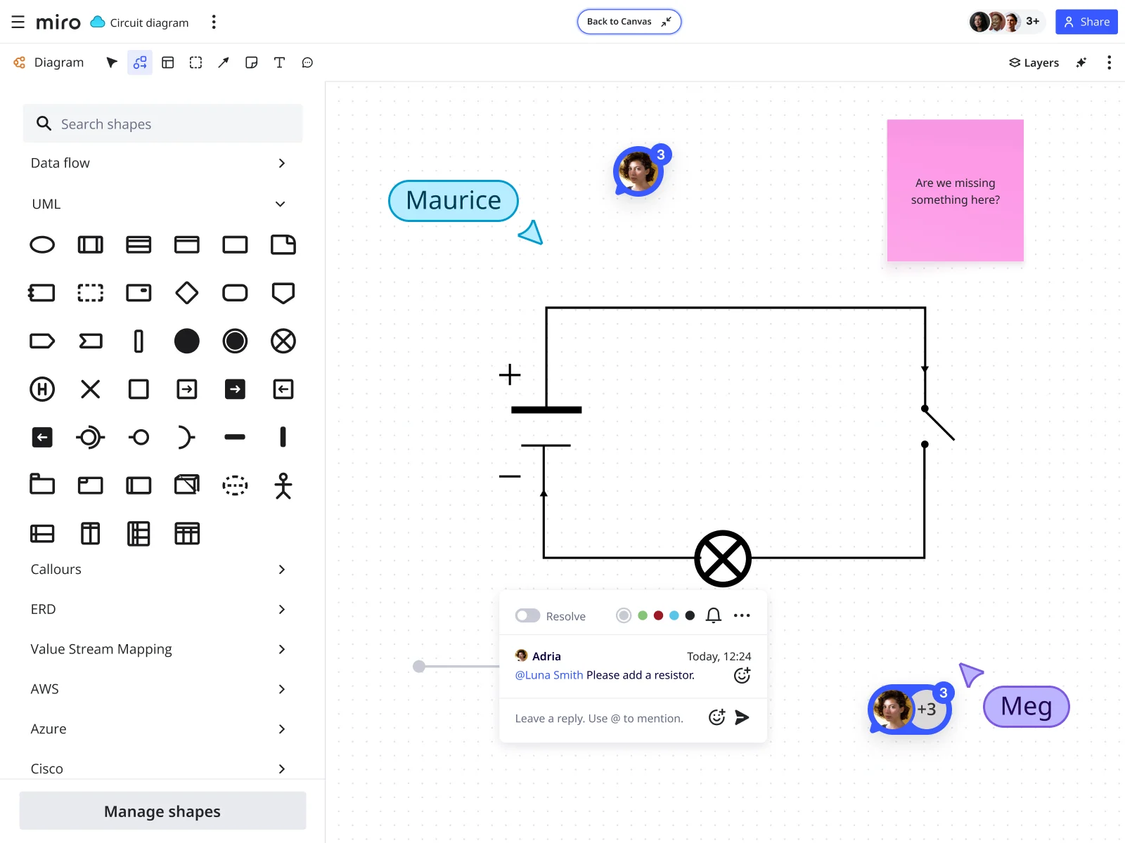
Step 6: Collaborate in real time
Invite electrical engineers, product managers, or anyone else who needs to review the design directly to your Miro board. Use comments to flag questions about component choices, sticky notes to capture ideas for circuit improvements, and voting to prioritize design decisions across the team.
Because everything lives on the Miro canvas, your circuit diagram sits alongside your project specs, architecture diagrams, and sprint plans — in one place, not five.
Step 7: Export your circuit diagram
Once your circuit is final, go to the three dots in the top left corner, click Board, then Export. Select Save as PDF for technical documentation or presentations, or export as an image to embed in reports or educational materials.
Series vs. parallel circuit diagrams: A quick comparison
Understanding the difference between a series circuit diagram and a parallel circuit diagram matters both for reading and drawing schematics correctly.
In a series circuit diagram, all components sit in a single loop. The same current passes through each one. Total resistance is the sum of all individual resistances. The main trade-off: one broken component interrupts the whole circuit. Classic use case: battery-powered flashlights with components in a chain.
In a parallel circuit diagram, components connect across the same two nodes. Each branch has the same voltage across it, but current divides between branches. Total resistance is lower than any individual branch. Components operate independently. Classic use case: household electrical outlets, where each appliance operates at the same voltage regardless of how many others are running.
Most real-world circuits are a combination of both. A typical amplifier circuit diagram, for instance, might use series resistors for biasing and parallel capacitors for filtering.
How ClickHouse uses Miro for collaborative technical diagramming
Keeping complex technical diagrams accurate and accessible across a growing distributed team is harder than it sounds. ClickHouse, the company behind one of the world's fastest analytical databases, figured this out firsthand.
Built on a complex AWS architecture and maintained by remote teams, ClickHouse needed a way to capture design decisions visually and make them accessible to anyone on the team: the original architect, a reviewer, or a new hire onboarding to the project.
"Every decision is recorded in a Miro diagram where the final design that's implemented is visualized," said Roopa Tangirala, Vice President of Engineering at ClickHouse, "which is especially useful for onboarding" because all the context anyone needs to get up to speed is stored on a single canvas.
What started as a design tool grew into a core part of planning across a team that scaled from two engineers to over 30. The result: improved collaboration, faster development cycles, and better visibility for everyone — from individual contributors to leadership.
Circuit diagrams face the same challenge. They need to be accurate, current, and reviewable by people who weren't in the room when the design was made. Keeping them on a shared Miro canvas, rather than locked in a file on someone's desktop, solves that problem directly.
Circuit diagrams in Miro: Why it works for engineering teams
Most diagramming tools are built for individual work. You create a schematic, export it, attach it to a ticket, and hope the right person opens the attachment before the design review. That workflow breaks down fast when you're working across time zones, multiple stakeholders, or fast-moving sprint cycles.
Miro's approach is different because the canvas is the collaboration layer. Your circuit diagram, your architecture diagram, your project plan, and your team's feedback all live in the same place. Engineers can comment directly on a specific component. Managers can see how a circuit decision connects to the broader product spec. New team members can read the full design history without chasing down anyone for context.
The 79 electrical engineering shapes — covering everything from basic resistors to logic gates, relays, and transistors — give you enough to build accurate, professional schematics without needing a specialist tool. And because Miro supports both real-time and async collaboration, your design review doesn't have to be a meeting.
Start building your circuit diagrams in Miro
Whether you're mapping out a simple circuit diagram for a proof of concept, reviewing a parallel circuit diagram with your hardware team, or documenting a full amplifier circuit diagram for a product handoff, Miro gives you everything you need in one place.
The shapes are there. The collaboration tools are there. And your team is already in Miro.
Sign up for free and start drawing your first circuit diagram today.
Circuit Diagram FAQs
What is a circuit diagram? A circuit diagram is a schematic that uses standardized symbols to represent the components of an electrical circuit and show how they're connected. It describes electrical function, not physical layout.
What are the most common circuit diagram symbols? The most common circuit diagram symbols include the battery (power source), resistor, capacitor, inductor, diode, LED, transistor, logic gates, ground, and connection lines. Miro includes 79 electrical engineering shapes across all major categories.
What is the difference between a series circuit diagram and a parallel circuit diagram? In a series circuit diagram, components connect in a single loop and share the same current. In a parallel circuit diagram, components connect across the same two nodes, share the same voltage, and operate independently. Most real circuits combine both configurations.
How do you read a circuit diagram? To read a circuit diagram, trace the current path from the positive terminal of the power source through each component and back to the negative terminal. Identify how components are connected (series or parallel), check labels for component values, and look for junction dots to understand which wires connect.
Can I collaborate on circuit diagrams in Miro? Yes. You can invite teammates to your Miro board to review, comment on, and edit circuit diagrams in real time or asynchronously. Comments, sticky notes, and voting features make it easy to gather feedback without scheduling a separate meeting.
How do I export a circuit diagram from Miro? Click the three dots in the top left corner of your Miro board, select Board, then Export. You can save your circuit diagram as a PDF or image file for documentation, presentations, or technical reports.
What is a short circuit diagram? A short circuit diagram illustrates an unintended low-resistance connection between two points in a circuit that allows current to bypass its intended path. Short circuit diagrams are used in troubleshooting and safety analysis to identify fault conditions.
Can I create an amplifier circuit diagram in Miro? Yes. Miro's electrical engineering shape library includes transistors, resistors, capacitors, voltage sources, and other components required to build amplifier circuit diagrams. You can map out biasing networks, gain stages, and filter configurations on the same canvas where your team reviews and documents the design.
Author: The Miro team Last updated: April 2, 2026