101 likes
2.1K uses
Architect your software with precision. The UML Class Diagram template allows you to visually map out your system’s structure, defining classes, attributes, and relationships to ensure a scalable and robust codebase.
3 templates
UML Class Diagram
A UML (Unified Modeling Language) Class diagram is a visual representation that shows the structure and relationships of classes in a system or software application.
UML Class Diagram Template
Get a template for quickly building UML class diagrams in a collaborative environment. Use the UML class diagram template to design and refine conceptual systems, then let the same diagram guide your engineers as they write the code.
A UML (Unified Modeling Language) Class Diagram template is a static structural diagram that describes the structure of a system by showing the system's classes, their attributes, operations (methods), and the relationships among objects. It is the most common diagram used in object-oriented modeling, acting as the bridge between conceptual design and actual code implementation.
A class diagram is only useful if a developer can build from it. Before finalizing your Miro board, apply these three expert "health checks":
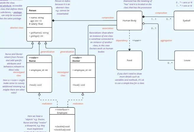
1. The "Encapsulation" Access Modifier AuditThe Audit: Are your attributes all public by default? The Fix: Audit your Visibility Symbols. In professional UML, you must define how data is accessed:
+ Public: Accessible by any other class.
- Private: Accessible only within the class (Best practice for attributes).
# Protected: Accessible by the class and its subclasses.
~ Package: Accessible by classes within the same package. If your template doesn't use these prefixes, it’s a sketch, not a technical specification.
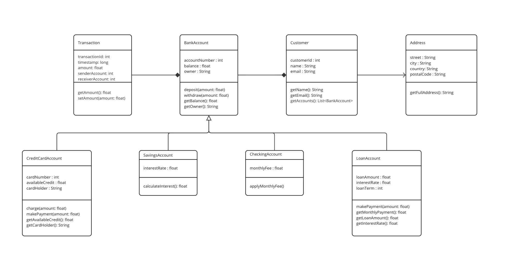
2. The "Multiplicity" (Cardinality) Test The Audit: Are your lines just connecting boxes without defining "How Many"? The Fix: Audit your Relationship Logic. Use numbers at the ends of your association lines to define the count:
1: Exactly one.
0..*: Zero or many.
1..*: One or many. Without multiplicity, the developer won't know if a "Customer" class should have a single "Order" variable or a List/Array of "Orders."
3. The "Inheritance vs. Composition" AuditThe Audit: Are you overusing "Is-A" (Inheritance) when you should use "Has-A" (Composition)? The Fix: Audit your Connector Types.
Generalization (Empty Triangle): Use for Inheritance (e.g., a "Car" is a "Vehicle").
Composition (Filled Diamond): Use for strong ownership (e.g., a "Car" has an "Engine"; if the car is destroyed, the engine is too).
Aggregation (Empty Diamond): Use for loose collections (e.g., a "Library" has "Books"; if the library closes, the books still exist).
A professional Class Diagram template uses a three-compartment rectangle for every entity:
Top Compartment (Class Name): The name of the class (Centered and Bold). If it's an Abstract Class, the name should be in Italics.
Middle Compartment (Attributes): The "Data" or variables. Format: [visibility] name : type = default_value.
Bottom Compartment (Operations): The "Behavior" or methods. Format: [visibility] name (parameter_list) : return_type.
The Conceptual Model:
Best For: Business Analysts and Initial Brainstorming.
The Goal: High-level entities and their real-world relationships without worrying about data types or return values.
The Design Model:
Best For: Developers and System Architects.
The Goal: Full technical detail, including private fields, getters/setters, and specific data structures.
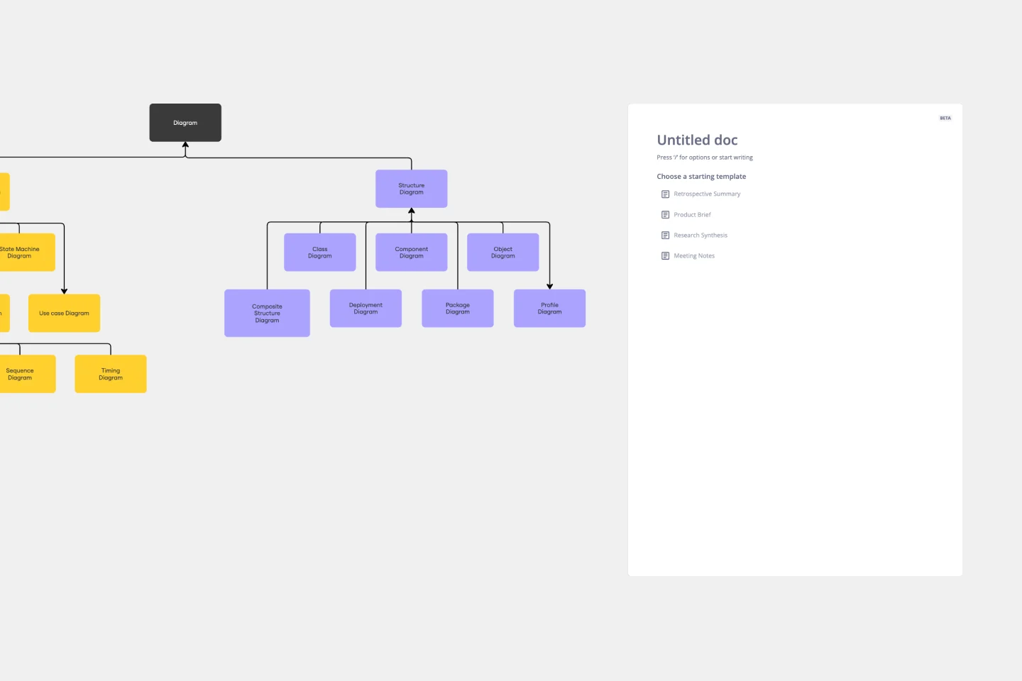
The "Spiderweb" Effect: Too many crossing lines that make the diagram unreadable.
The Fix: Use Packages (folders) to group related classes and reduce the number of long-distance connections.
Modeling "Every" Method: Including standard constructors or trivial getters/setters.
The Fix: Focus on the Unique Logic. If a method doesn't add architectural value, leave it out to keep the diagram clean.