Table of contents
Table of contents
What is a use case diagram?
Summary
In this guide, you will learn:
- What a use case diagram is and its role
- Key components: actors, use cases, relationships, system boundaries
- How use case diagrams capture requirements and define scope
- Common UML notations and symbols
- Purposes and benefits throughout the software development lifecycle
- Best practices for creation and use
Collaborative AI Workflows
Join thousands of teams using Miro to build the right thing, faster.
Use case diagrams explained
Have you ever found yourself scratching your head, wondering how to clearly communicate system functionalities to your team? If so, use case diagrams might be the tool you need. Let's dive into the world of use case diagrams, where visual clarity meets functional depth, making your job a lot easier.
What is a use case diagram?
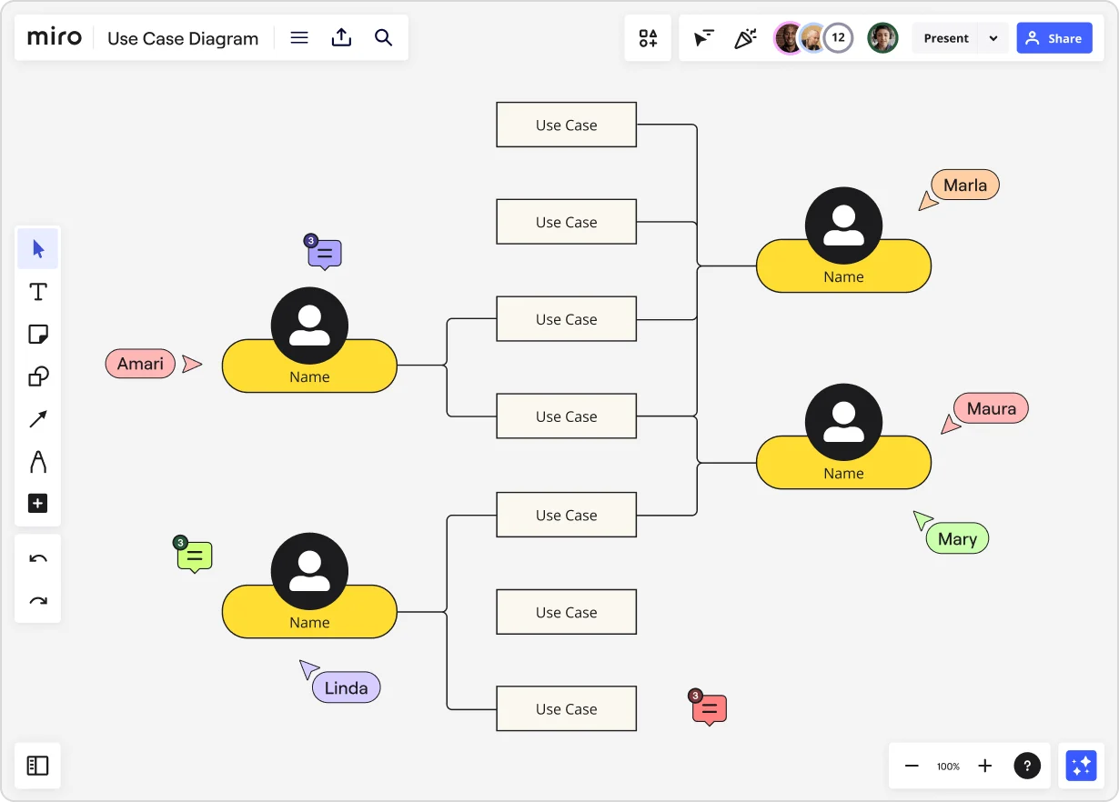
A use case diagram is like a blueprint for your system’s functionality. It visually represents the interactions between users (or "actors") and the system itself, highlighting the various ways the system can be used. Think of it as a high-level map that lays out the different paths users might take to achieve their goals within the system. This map helps everyone involved—from developers to stakeholders—understand the system's capabilities and interactions clearly.
By providing a visual overview, use case diagrams make complex systems more accessible and easier to understand. They are a crucial tool in the early stages of system design and development, ensuring that all stakeholders have a unified understanding of how the system will function.
Components of a use case diagram
Breaking down a use case diagram into its fundamental components can demystify its structure and make it easier to create and understand. Here’s what you need to know:
Actors
Actors are the entities that interact with your system. They can be users, other systems, or even hardware. For example, in a banking application, actors might include customers, bank tellers, and the bank’s internal systems.
Primary actors: These are the users or entities that directly interact with the system to achieve a goal.
Secondary actors: These are the entities that provide services to the system, often indirectly involved in the primary use case.
External systems: These are systems outside of your own that interact with it, such as payment gateways or third-party APIs.
Use cases
Use cases are the specific actions or services the system provides to the actors. Each use case represents a goal that an actor can achieve by interacting with the system.
Core functions: These are the primary actions that the system supports, such as "Withdraw Money" or "Check Balance" in a banking system.
Sub-functions: These are secondary functions that support the core actions, like "Print Receipt" after withdrawing money.
Exception handling: These use cases handle exceptions or errors that might occur during a primary use case, such as "Insufficient Funds."
Associations
Associations are the lines connecting actors to use cases. They illustrate their interactions. For instance, a line between a customer actor and the "Withdraw Money" use case shows that customers can withdraw money from the banking system.
Direct associations: Straightforward interactions between actors and use cases.
Indirect associations: Involves secondary actors or systems that support the interaction.
System boundary
The system boundary defines what is included in the system you’re diagramming. It’s represented by a rectangle that encapsulates all the use cases. Anything outside this boundary is not part of the system but may interact with it.
System scope: Defines the limits of the system.
External interactions: Identifies interactions with actors outside the system.
Communication paths
Communication paths show how actors and use cases interact. They help clarify the flow of information or actions between the actors and the system. These paths are essential for understanding and optimizing system interactions.
Data flow: Shows how data is passed between actors and use cases.
Action flow: Illustrates the sequence of actions or operations that occur.
How to create a use case diagram with Miro
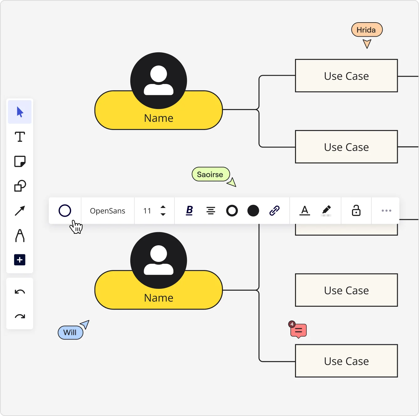
Creating use case diagrams can be a breeze with Miro, your go-to visual workspace for innovation. Here's a step-by-step guide to get you started:
- Set up your workspace: Log in to Miro and create a new board. Use Miro’s pre-built templates to get a head start on your use case diagram.
- Identify actors and use cases: List out all the actors and use cases you need to include. Use Miro’s sticky notes or shapes to represent these elements.
- Draw associations: Connect actors to their corresponding use cases with lines. Miro’s intuitive drag-and-drop interface makes this simple and efficient.
- Define system boundaries: Use a rectangle to encapsulate all your use cases, clearly defining what’s inside your system.
- Add communication paths: Illustrate the flow of interactions between actors and use cases to complete the diagram.
Miro’s real-time collaboration features allow your team to work together seamlessly, making it easy to iterate and refine your diagrams on the fly. With integrations like Jira, Asana, and Azure, you can import tasks and issues as interactive cards on your board, making your workflow even more efficient.
Use case diagram examples
To get a clearer picture, let’s look at some concrete examples of use case diagrams in action. These examples will illustrate the various components and how they interact within different systems.
ATM machine
Imagine you’re designing an ATM system. The actors might include customers and bank staff. Use cases could be "Withdraw Cash," "Deposit Funds," and "Check Balance." The system boundary would encapsulate these use cases, showing the functionalities the ATM provides.
When it’s used: An ATM use case diagram is typically used during the design and development phase of banking software to ensure all necessary functionalities are covered and interactions are clear.
Components:
Actors:
- Customer
- Bank staff
Use cases:
- Withdraw Cash
- Deposit Funds
- Check Balance
- Associations: Lines connecting customers to all use cases and bank staff to administrative functions.
- System boundary: Encloses all use cases to define the ATM's scope.
- Communication paths: Illustrate the steps taken by customers to perform each transaction, and by staff to manage the machine.
E-commerce website
For an e-commerce site, actors might be customers, admins, and payment gateways. Use cases could include "Browse Products," "Make Purchase," "Manage Inventory," and "Process Payment." This diagram helps visualize the interactions between different actors and the system's functionalities.
When it’s used: This diagram is used in the planning stages of an e-commerce platform to ensure a smooth user experience and efficient backend processes.
Components:
Actors:
- Customer
- Admin
- Payment Gateway
Use cases:
- Browse Products
- Make Purchase
- Manage Inventory
- Process Payment
- Associations: Connections between customers and browsing/purchasing, admins and inventory management, and payment gateways with purchasing.
- System boundary: Defines what part of the online shopping experience is handled by the system.
- Communication paths: Show how users interact with the site, how admins manage inventory, and how payments are processed.
Mobile app
In a mobile app scenario, actors might be end-users and backend services. Use cases could include "Login," "Send Message," and "Receive Notifications." This helps map out how users interact with the app and what the backend needs to support.
When it’s used: During the design and development phase to outline key user interactions and backend requirements.
Components:
Actors:
- End-user
- Backend Service
Use cases:
- Login
- Send Message
- Receive Notifications
- Associations: Lines showing interactions between end-users and use cases, backend services, and use cases.
- System boundary: Encloses the functionalities provided by the mobile app.
- Communication paths: Detail the flow of user inputs and system responses.
Software system
For a complex software system, actors might include developers, QA testers, and end-users. Use cases could be "Submit Bug Report," "Run Tests," and "Deploy Code." The Use case diagram in software engineering is invaluable for understanding how different parts of the software development lifecycle interact.
When it’s used: Throughout the development lifecycle to ensure all roles and interactions are covered.
Components:
Actors:
- Developer
- QA Tester
- End-user
Use cases:
- Submit Bug Report
- Run Tests
- Deploy Code
- Associations: Connections between actors and their respective use cases.
- System boundary: Defines the scope of the software system.
- Communication paths: Show the workflow from development to testing to deployment.
Business process
In a business process context, actors might include employees and management. Use cases could be "Approve Leave," "Submit Expense Report," and "Conduct Performance Review." This helps streamline business operations and improve process efficiency.
When it’s used: During the optimization of business processes to improve efficiency and clarity.
Components:
Actors:
- Employee
- Manager
Use cases:
- Approve Leave
- Submit Expense Report
- Conduct Performance Review
- Associations: Lines connecting employees to their tasks and managers to approval processes.
- System boundary: Encloses the business processes under consideration.
- Communication paths: Detail the steps in each process, ensuring clarity and efficiency.
When to use a use case diagram and benefits
Use case diagrams are versatile tools that can be applied in various scenarios. Here’s when and why you should consider using them:
System design and analysis
Use case diagrams provide a clear overview of system functionalities and interactions, making them essential for system design and analysis. By mapping out user interactions, you can identify key requirements and potential bottlenecks early in the design process.
Identify requirements: Clearly outline what the system must do to meet user needs.
Visualize interactions: Understand how different parts of the system work together.
Optimize design: Identify and resolve potential issues before development begins.
Requirement gathering
They help gather and document system requirements, ensuring that all stakeholders have a common understanding of the system’s capabilities. Use case diagrams serve as a communication bridge between technical and non-technical stakeholders.
Unified understanding: Ensure everyone is on the same page regarding system capabilities.
Stakeholder engagement: Engage all stakeholders in the requirements-gathering process.
Clear documentation: Provide clear and visual documentation of requirements.
Communication
These diagrams enhance communication among team members, stakeholders, and clients by providing a visual representation of the system. Visuals are often easier to understand than text-based descriptions, making it simpler to convey complex information.
Simplify complex concepts: Make complex systems understandable at a glance.
Align team efforts: Ensure all team members are working towards the same goals.
Facilitate feedback: Make it easier for stakeholders to provide feedback.
Problem identification
They can help identify potential issues and bottlenecks in system interactions, allowing for proactive problem-solving. By visualizing the system’s interactions, you can pinpoint where things might go wrong and address them early.
Early detection: Spot issues before they become major problems.
Improve system efficiency: Identify and remove bottlenecks in the system.
Enhance user experience: Ensure a smooth and seamless interaction for users.
Documentation
Use case diagrams serve as valuable documentation for current and future reference, ensuring consistency in understanding and implementation. They provide a historical record of system functionalities and user interactions.
Maintain consistency: Ensure consistent understanding and implementation over time.
Historical reference: Keep a record of system changes and developments.
Training tool: Use diagrams to train new team members or stakeholders.
Activity diagram vs. use case diagram
When planning and designing systems, it’s essential to choose the right diagram for the task. Both activity diagrams and use case diagrams are valuable tools, but they serve different purposes and offer unique benefits. Let’s explore the differences and when to use each one.
Purpose and focus
Use case diagrams are primarily focused on the interactions between actors (users or external systems) and the system itself. They provide a high-level overview of what the system does and who interacts with it. Use case diagrams are excellent for outlining the functionalities of a system and identifying user requirements.
Activity diagrams, on the other hand, are more concerned with the workflow and the sequence of activities within a system. They detail the steps involved in a particular process, showing how one activity leads to another. Activity diagrams are useful for modeling the flow of control or data within a system, making them ideal for analyzing and optimizing processes.
Components
Use case diagram components:
- Actors: Entities interacting with the system.
- Use cases: Actions or services the system provides.
- Associations: Connections between actors and use cases.
- System boundary: Defines the scope of the system.
- Communication paths: Show interactions between actors and use cases.
Activity diagram components:
- Activities: Steps or tasks performed within the system.
- Transitions: Arrows showing the flow from one activity to the next.
- Decision points: Diamonds indicating branching paths based on conditions.
- Start and end nodes: Represent the beginning and end of the workflow.
- Swimlanes: Dividers that organize activities by actor or system component.
Usage scenarios
When to use use case diagrams:
- System design and analysis: For identifying system functionalities and user interactions.
- Requirement gathering: To document and communicate user requirements.
- High-level planning: When needing a broad overview of system capabilities.
When to use activity diagrams:
- Process modeling: To detail the steps and flow of a process or workflow.
- Detailed analysis: For examining the sequence of activities and identifying inefficiencies.
- Operational optimization: To streamline processes and improve system performance.
Benefits
Use case diagram benefits:
- Clarity in functionality: Provides a clear overview of what the system does.
- Improved communication: Helps align team members and stakeholders on system capabilities.
- Requirement documentation: Serves as a visual tool for documenting user requirements.
Activity diagram benefits:
- Detailed process flow: Offers a granular view of the steps involved in a process.
- Optimization insights: Helps identify bottlenecks and areas for improvement.
- Enhanced understanding: Clarifies the sequence and flow of activities within the system.
Visual representation
Use case diagrams are typically less detailed but broader in scope, focusing on interactions and overall functionalities. They are best suited for presentations to stakeholders and high-level planning sessions.
Activity diagrams are more detailed and provide a step-by-step breakdown of processes. They are ideal for technical teams looking to optimize workflows and ensure efficient operation.
Choosing the right tool
When deciding between a use case diagram and an activity diagram, consider the following:
Goal: Are you identifying system functionalities (use case diagram) or detailing process steps (activity diagram)?
Audience: Are you presenting to stakeholders and gathering requirements (use case diagram) or optimizing internal workflows (activity diagram)?
Detail level: Do you need a high-level overview (use case diagram) or a detailed process map (activity diagram)?
By understanding the strengths and applications of each diagram type, you can choose the right tool for your specific needs, ensuring effective communication and efficient system design.
Use case diagram best practices
To make the most out of your use case diagrams, follow these best practices:
Keep it simple
Avoid overcomplicating your diagram. Stick to essential actors and use cases to maintain clarity. Overloading the diagram with too many details can make it hard to understand and less effective as a communication tool.
Focus on essentials: Include only the most critical actors and use cases.
Avoid overcrowding: Ensure the diagram is clean and easy to read.
Use clear labels: Label each component clearly to avoid confusion.
Be consistent
Use consistent naming conventions and symbols throughout your diagram to avoid confusion. Consistency helps ensure that everyone interprets the diagram in the same way.
Standardize symbols: Use standard UML symbols for clarity.
Consistent naming: Use consistent names for actors and use cases.
Uniform layout: Maintain a uniform layout for better readability.
Focus on user goals
Ensure your use cases reflect the users' actual goals and needs. This user-centric approach helps create a system that truly meets users’ expectations.
User-centric design: Base use cases on user needs and goals.
Prioritize key functions: Focus on the most important user interactions.
Gather user feedback: Involve users in the diagramming process.
Iterate and refine
Refine your diagrams using feedback from your team. Miro’s collaboration features make this process smooth and efficient. Regularly updating and improving your diagrams ensures they remain accurate and useful.
Collaborative feedback: Gather input from all team members.
Regular updates: Keep diagrams up-to-date with system changes.
Continuous improvement: Refine diagrams based on feedback and new insights.
Power integrations
If your use case diagrams are part of a larger system or workflow, you can benefit from Miro’s integrations with tools like Jira, Asana, and Azure to import tasks and issues as interactive cards on your board. This integration capability helps streamline your workflow and ensures all relevant information is easily accessible.
Seamless integration: Connect with other tools for a unified workflow.
Interactive boards: Import tasks and issues for dynamic interaction.
Enhanced productivity: Improve efficiency with integrated tools.
Create use case diagrams with confidence
In summary, use case diagrams are powerful tools that can improve your system design, requirement gathering, and overall communication. With Miro, your visual workspace for innovation, creating these diagrams is not only easy but also collaborative and efficient. Start using use case diagrams today to bring clarity and efficiency to your product development process.
Author: Miro Team
Last update: October 14, 2025