Table of contents
Table of contents
What is a UML Communication Diagram?
Summary
In this guide, you will learn:
- What a UML communication diagram is and how it differs from other interaction diagrams.
- Key components and notations of communication diagrams: objects, messages, and links.
- How to visualize and label message flows using arrows and sequencing numbers.
- The purpose of communication diagrams in illustrating object interactions and message passing.
- Steps and best practices for creating clear, readable communication diagrams.
- How to finalize, test, and collaborate on communication diagrams.
Collaborative AI Workflows
Join thousands of teams using Miro to build the right thing, faster.
Understanding UML Communication Diagrams
A system architecture is the backbone of all application or software processes, actions, and interactions.
To create this architecture as a blueprint you can collaborate on, you'll need UML diagrams to visualize the system in different capacities. UML communication diagrams, in particular, visualize the exchange of messages between objects and actors in a system. They are often used in the early stages of software design to flesh out the details of how objects interact.
In this guide, you'll learn the foundations of creating UML communication diagrams — what they look like, when to use them, and how to use them effectively.
Introduction to UML communication diagrams
Communication diagrams visualize an overview of messages sent between objects and actors within a system, process, or function. In UML, communication diagrams are considered a type of behavioral diagram, alongside sequence diagrams and interaction diagrams.
Imagine the UML communication diagram for an automated teller machine (ATM) to get an idea. To dispense money to a user, the user (or actor) sends a message to the ATM by inserting a card and PIN code. The ATM then sends a message to the bank to show the user's account info. Finally, the bank sends an approval message to the ATM, and the user receives the money.
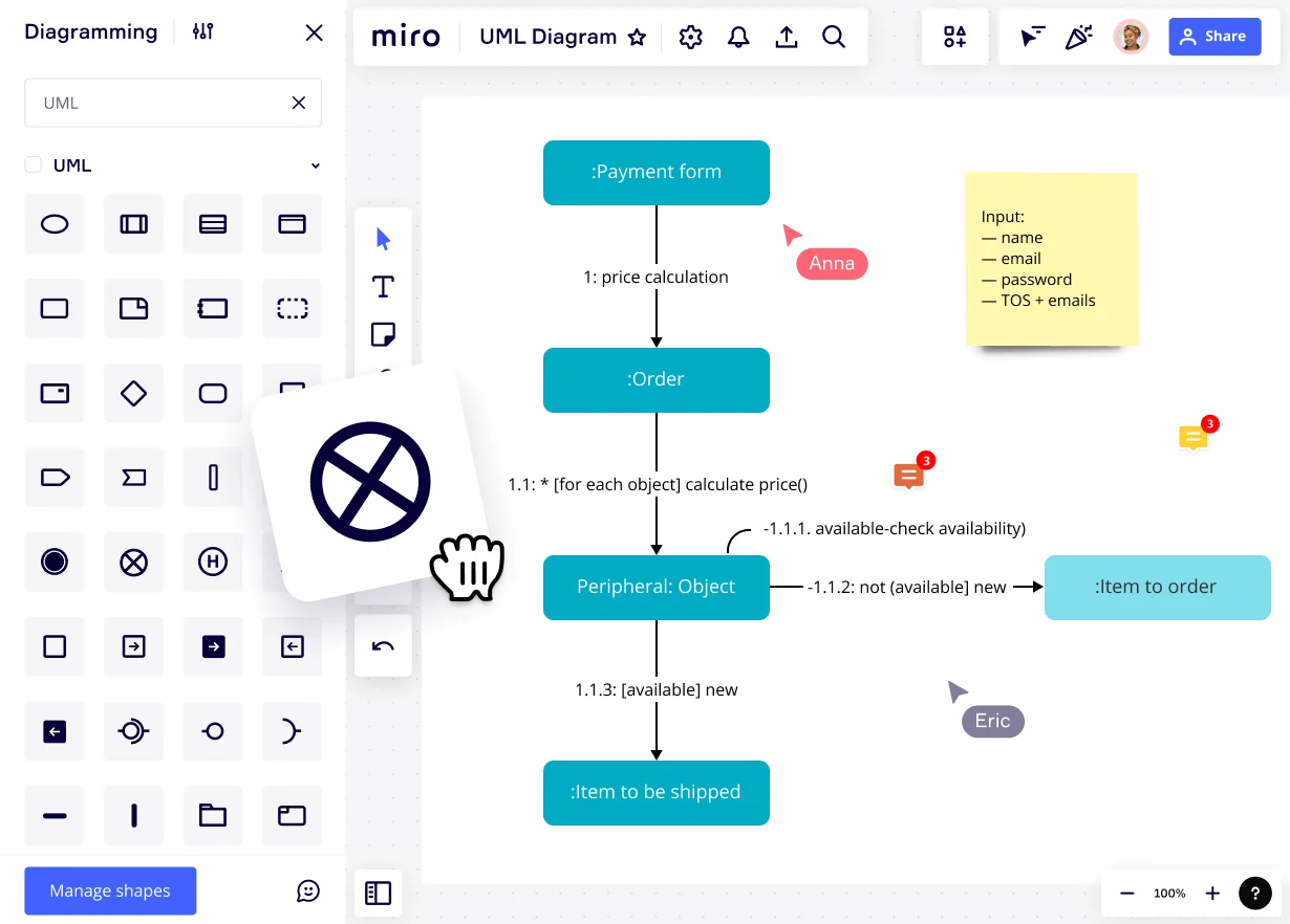
Visually, all messages in the communication diagram are clearly stated, along with their direction, precedence, and order number with decimals to show dependencies. All objects, represented as rectangles, are connected with straight lines and arrows.
Purpose of UML communication diagrams
The main purpose of a UML communication diagram is to show the messages that objects send to one another (or themselves) to make the system do what a use case specifies.
UML communication diagrams are useful during design to visualize the proper sequence of messages between objects and actors. Mapping this out helps developers and programmers save time and energy, plus avoid making mistakes early on. These diagrams also serve as documentation for future changes, updates, and redesigns. Just as blueprints help with house renovations.
When to use a UML communication diagram
UML communication diagrams are typically created before the development of a system to map out what needs to be built and how. The purpose of diagramming messages and interactions between objects is to achieve a functionality or behavior stated in a use case or function.
More specifically, you'd want to use a UML communication diagram to depict the sequence of messages or information. They model the flow of messages (and the order in which they occur) between objects or between a user and objects.
Benefits of UML communication diagrams
UML communication diagrams offer many benefits for effective system diagramming, development, and building of system architecture:
Easy to interpret
UML communication diagrams clarify the role of each object or actor in a system. Notations and shapes show the messaging relationship within parts of the system.
Show sequential information
UML communication diagrams are essential for understanding the sequence and flow of messages between objects — like what order they're in and what messages depend on others.
Visualizes complex systems
Communication diagrams help visualize complex logic chains that involve multiple objects through clear notations. A complete communication diagram offers an overview of a system (or parts of it) without the need for further explanation.
Helps with future iterations
It's easier to plan new functions and scenarios for a system using a UML communication diagram. Ideally, the system's diagrams are updated regularly, so visualizing and prototyping a new feature is simple and intuitive.
Sequence vs. communication diagrams
Sequence and communication diagrams are both behavioral interaction UML diagrams. They visualize how a system or program behaves via messages exchanged between objects or actors.
The difference is that the sequence diagram shows a process unfolding over a specified time, while the communication diagram for the same system shows all involved objects in a single space as an overview of exchanged messages.
In a communication diagram, it's easier to see the overview of relationships among all the objects that participate in a particular task, function, or use case. In a sequence diagram, you see the timing of each message exchange and how one leads into another.
Creating a UML communication diagram
Building a UML communication diagram is easier when you have the right building blocks. When creating a communication diagram from scratch, be sure to stay within UML guidelines and keep communication with developers as clear as possible. Follow these steps to begin creating one:
1. Decide what function(s) to model
Outline what function or system the diagram will model. List the actor, objects, and messages. For example, a function can be a client withdrawing money from the ATM. You'd need a different communication diagram or a combination of both to visualize when a user uses the ATM to pay a bill.
However, note that the more actions and messages you visualize, the more complex the diagram will get. It's simpler to have a communication diagram per complete action.
2. Add connected shapes and figures for the objects and actor
Add rectangle shapes to your canvas. For each object, add one rectangle and name it. Place them on the canvas with space between each other. Add the actor as a stick figure if there is an actor. Actors can also be shown as rectangles, but stick figures visualize it better.
Start visualizing the sequence of messages by connecting the actor and the objects with lines. Straight lines determine that there is a connection between the shapes, and the arrows for message directions come after.
3. Use arrows to visualize messages between objects
Place arrows next to the lines that connect the objects. Each arrow represents one message, and the arrow direction visualizes which object sends the message and which one receives it. Use the same visual arrow style throughout the diagram.
Some objects communicate with other objects that aren't directly connected and are in another position of the sequence. Your arrows don't need to be straight to reach each object; they can bend to accommodate the space.
If the lines are too close together, they get difficult to read, so ensure balanced spacing between lines, arrows, objects, and the message text.
4. Label the arrows with numbers and text
On each arrow, add the message ID and the sequencing number to denote what the message is and what order it's in. Follow UML best practices for message number sequencing and labeling by sticking to industry fonts and sizes. These numbers are key to understanding exactly how messaging works within the system.
5. Finalize and share the communication diagram
Organize and adjust the objects neatly on the diagram so the message exchange makes sense and is intuitive to follow. Use colors to differentiate object types and message sequences. Test the diagram by turning it into a sequence diagram. If the sequence is flawed, return to the communication diagram and adjust the number sequencing or arrow directions.
Collaborate with stakeholders to review and finalize the UML communication diagram for your system. Follow the message flow together to ensure everything is satisfactory and visualizes the completion of an action.
Notation and symbols in UML communication diagrams
Like all UML diagrams, communication diagrams consist of notations and symbols that visualize a system's behavior. In the case of communication diagrams, notations focus on the exchange of messages and their sequence in the process.
Actors
Actors are the users or entities that interact with the system. They're human users, organizations, event triggers, or other systems. In a UML communication diagram, they're visualized as stick figures if they're people or another shape to signify the user.
Typically, in a UML diagram, the actor is depicted on the top left of the diagram, signifying the beginning point for the sequence of messages. Label the actor accordingly using the same font type as the message IDs in the diagram.
Objects and shapes
Objects are typically represented as rectangles. Choose one style and stick to it for the entire diagram. Color code them by characteristics, groups, direct sequences, or dependencies.
Links, lines, and arrows
Lines and arrows in a UML communication diagram are notations for connection and relationship. The straight line connects objects to visualize their relationship. When objects aren't connected to a line, they're considered separate and independent from each other.
Arrows denote the direction of the relayed message between objects. Use the same arrow style throughout your diagram to avoid visual confusion. Also, use the same spacing between the line and arrow so there's enough space for the numbers and the messages.
When two connected objects send each other a message, place each arrow and notation on either side of the connecting line.
Numbers
Number notations detail the order of messages between objects and the actor – group messages by using decimals to denote a parent and dependents. Messages always start at 1, then 2, 3, etc. Number the messages in group 1 like this; 1.1, 1.2, 1.3, and so on.
When turning a communication diagram into a sequence diagram, these numbers are the blueprint for how the objects are placed and laid out to visualize the sequence based on time.
Messages
Messages follow UML capitalization guidelines and use camel case. Each word, except the first, is capitalized, and there's no space between the words. First, add the order and sequence number, then a colon, and finally, the message in a short ID or abbreviated name. Like this, '1.1 : inputPin'.
To write messages, use a simple sans font like Arial or Open Sans. Maintain the same font size throughout the diagram and ensure the text is easy to read over the background when using color.
Create your own UML communication diagram
A system's visual architecture displays all the interconnected parts and how they relate to each other. It does so in a way that's simple for developers, designers, programmers, and stakeholders to understand.
UML diagrams are the optimal choice for building a system's blueprint for behavior and structure. They help programmers, developers, and designers communicate with each other about the inner workings of a system they're working on together.
UML communication diagrams, in particular, are key to visualizing how objects communicate inside a system. Notations and symbols like arrows, lines, and numerals show the message order and direction between the objects.
Get started with your own UML communication diagram by following this guide — or use Miro’s UML Communication Diagram Template to help guide you.
Author: Miro Team
Last update: October 10, 2025