Block diagram reduction — the ultimate guide
Summary
In this guide, you will learn:
- What block diagram reduction is and how it simplifies complex system diagrams
- The fundamental principles of block diagram reduction, including standardized symbols and rules for combining blocks
- A step-by-step approach to block diagram reduction, from selecting tools to organizing the initial diagram
- How block diagram reduction improves clarity, troubleshooting, and system analysis
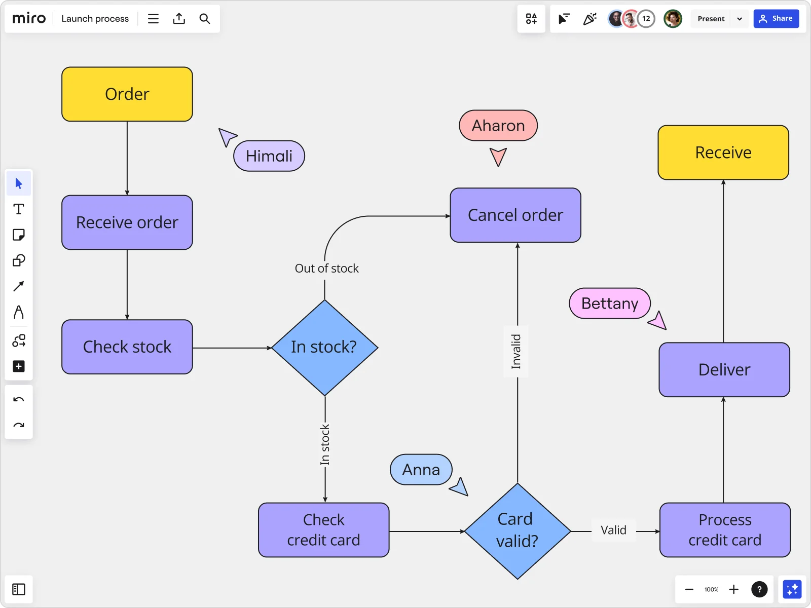
- The advantages of using Miro’s visual workspace and block diagramming tools for real-time collaboration
- Practical tips for applying block diagram reduction techniques within Miro for clear and accurate system representations
Collaborative AI Workflows
Join thousands of teams using Miro to build the right thing, faster.
What is block diagram reduction?
Block diagram reduction simplifies complex systems you often see in control system engineering and various other fields. Think of it as a way to clean up and streamline complex diagrams so that they're easier to manage while keeping all the crucial details intact.
By reducing block diagrams, we make complex systems less daunting and more approachable. This helps anyone – whether you're a seasoned engineer or a newbie – get a clearer picture, troubleshoot problems, and analyze systems more effectively.
In this guide, we'll walk you through everything about block diagram reduction. You'll learn the fundamental principles, see how it's applied, and follow a step-by-step approach to mastering this technique.
Let’s dive in.
Basic principles of block diagram reduction
A block diagram visually breaks down a system using blocks and lines. The blocks represent different components or subsystems, and the lines show how signals or information flow between these components. The goal of reduction is to simplify these diagrams. This not only makes them easier to understand but also helps identify and remove any unnecessary parts.
Here's a straightforward rundown of the key principles you need to know:
Use standardized components and symbols
Block diagrams use a variety of symbols to represent different actions, inputs, outputs, and decisions. Standardizing these symbols is crucial — it helps make sure everyone can easily understand and follow the diagrams, regardless of their background or expertise.
Follow established rules and techniques
Block diagram reduction isn't random; it follows a precise set of rules. These rules help us manage everything from parallel paths to series connections and feedback loops. By sticking to these guidelines, we can make sure that the simplified diagram accurately reflects the system, helping avoid any confusion or misinterpretation.
Benefits of block diagram reduction
Block diagram reduction brings several advantages to the table, especially when you’re analyzing and designing systems in fields like control system engineering. Let’s look at some of the major benefits:
Streamlines complex systems
Block diagram reduction simplifies complex systems visually, making them easier to grasp and work with. By cutting out the clutter and merging blocks, we make these systems more straightforward and digestible. This clear view helps anyone involved – from engineers to project managers – solve problems more effectively.
Improves understanding and communication
A cleaner, reduced block diagram means better clarity. It becomes much easier for everyone, whether they're engineers, researchers, or analysts, to see the critical parts and how they connect.
This clarity not only helps in understanding how the system behaves but also enhances discussions with team members, clients, and other stakeholders. A simple diagram can communicate the essentials of a system much more effectively than a complex one.
Facilitates system analysis and design
With block diagram reduction, insights into the inner workings of a system become instantly accessible. This allows engineers and designers to quickly identify and address inefficiencies.
A simplified diagram also makes it easier to apply mathematical methods and tools for analyzing dynamics, stability, and performance. This is crucial for tasks like calculating transfer functions and assessing how the system responds under different conditions.
Block diagram reduction in specific fields
Block diagram reduction isn’t just great in control system engineering but also in electrical engineering and various other fields.
Let’s explore some of the key areas where it makes a big difference:
Control systems engineering
In control systems engineering, block diagrams are fundamental. They map out system dynamics, crucial for crafting effective control strategies that enhance system performance. Simplifying these diagrams helps engineers see the big picture and fine-tune operations more efficiently.
Electrical circuit design
For electrical circuit designers, block diagrams are indispensable. They provide a clear layout of circuit elements and their interconnections, streamlining both the design and troubleshooting processes. This clarity helps minimize errors and improve overall efficiency, making the engineer's job much easier.
Business process modeling
Block diagram reduction also extends into fields like business process modeling, where it may not be as expected. In this context, it clarifies complex workflows, significantly boosting operational efficiency and improving communication across departments.
Step-by-step guide to block diagram reduction
Block diagram reduction isn't just about simplifying diagrams—it's about making complex systems easier to understand and work with. Let's walk through a methodical approach to reducing a block diagram, ensuring accuracy and clarity every step of the way.
Step 1: Select the right tools
While making a block diagram can be a daunting task, it can be a breeze with the right tools.
Miro, for example, is a powerful visual workspace with a user-friendly, drag-and-drop interface. Teams can collaboratively create diagrams and view entire systems at a glance—all on a single platform.
Step 2: Understand the system
Get a solid grip on the system’s architecture before diving into reduction. Identify all crucial elements, including subsystems, feedback loops, and individual components. This foundational understanding is key.
Step 3: Organize the initial block diagram
Start by constructing your initial diagram with standardized symbols. Make sure each component accurately represents a part of the system, capturing the complete process flow clearly.
Step 4: Identify parallel paths and series blocks
Spot any parallel paths within the diagram. Simplify these by adjusting the transfer functions of the parallel blocks—either adding or subtracting them as needed. Also, pinpoint any series blocks, which can be simplified by multiplying their transfer functions.
Step 5: Manage feedback loops
Feedback loops need special attention. Remove these by applying the right feedback formula, often involving subtracting the feedback path from the main loop.
Step 6: Apply reduction rules repeatedly
Keep applying the basic reduction rules, methodically working through the diagram to pare it down to its simplest form. Repeat the steps as necessary to refine further.
Step 7: Verify the reduced diagram
Ensure the reduced block diagram still accurately represents the system. Use mathematical analysis or simulation tools for verification, making sure the diagram maintains its integrity.
Step 8: Document and share
Once you've successfully reduced the diagram, document the process and share it with your team. Proper labeling, annotations, and storing the diagram in an accessible format will help everyone stay on the same page and use the diagram effectively.
Advanced techniques in block diagram reduction
As we dive deeper into block diagram reduction, we start tapping into more advanced techniques. These go beyond the usual tricks of the trade, using sophisticated mathematical tools and concepts to really get to the heart of complex systems.
Mason's gain formula
Mason's Gain Formula is a powerful tool used to determine the overall transfer function of a system from its block diagram. It considers all possible paths within the diagram and offers a systematic way to calculate the system's transfer function.
Signal flow graphs
Signal Flow Graphs offer an alternative way to represent systems that can be particularly useful in block diagram reduction. These graphs provide a visual method to understand and analyze how signals flow within a system, helping to identify key relationships and simplification opportunities.
Inverse signal flow graphs
Inverse Signal Flow Graphs are used to simplify complex systems by reversing the direction of signal flow. This unique approach can uncover new insights and significantly aid in the reduction process.
Merging blocks with feedback loops
When it comes to handling blocks with feedback loops, advanced techniques are necessary. This process involves a detailed analysis of the feedback structure and may require the use of sophisticated control system analysis tools to effectively merge and simplify these elements.
Every process has its potential pitfalls, and block diagram reduction is no exception. Misinterpreting symbols or connections can lead to errors that undermine system analysis. That's why it's crucial to have proper training and familiarity with standards to avoid these pitfalls.
Regular reviews, sticking to best practices, and getting peer verification can help mitigate the risk of errors in block diagram reduction.
On top of that, studying real-world examples of mistakes can be really helpful. These cases highlight the importance of accuracy in block diagram reduction and demonstrate how even small errors can result in significant failures.
Simplify your block diagram in Miro
Streamline your block diagram reduction process with Miro, a powerful visual workspace with advanced diagramming and mapping capabilities — including block diagramming tools.
Collaborate on your block diagram in real time, brainstorm ideas, and visualize complex systems effortlessly.
Sign up now to try it out for yourself!
Author: Miro Team
Last update: October 7, 2025