Table of contents
Table of contents
UML object diagrams: A guide
Summary
In this guide, you will learn:
- What a UML object diagram is and how it represents specific instances of classes at a particular moment in time
- The differences between UML object diagrams and class diagrams
- The purpose and benefits of using object diagrams to capture system snapshots and illustrate runtime scenarios
- The key elements and notation used in object diagrams
- Common use cases for object diagrams
- How object diagrams complement class diagrams to provide a more complete understanding of a system’s structure and behavior
Collaborative AI Workflows
Join thousands of teams using Miro to build the right thing, faster.
UML object diagrams are a cornerstone in the field of software engineering, offering a snapshot of a system at a particular moment. They are instrumental in depicting the practical instances of the classes and interfaces defined in class diagrams.
Let's dive into the dynamic world of UML object diagrams and unlock their potential in simplifying and clarifying software development processes.
What is an object diagram?
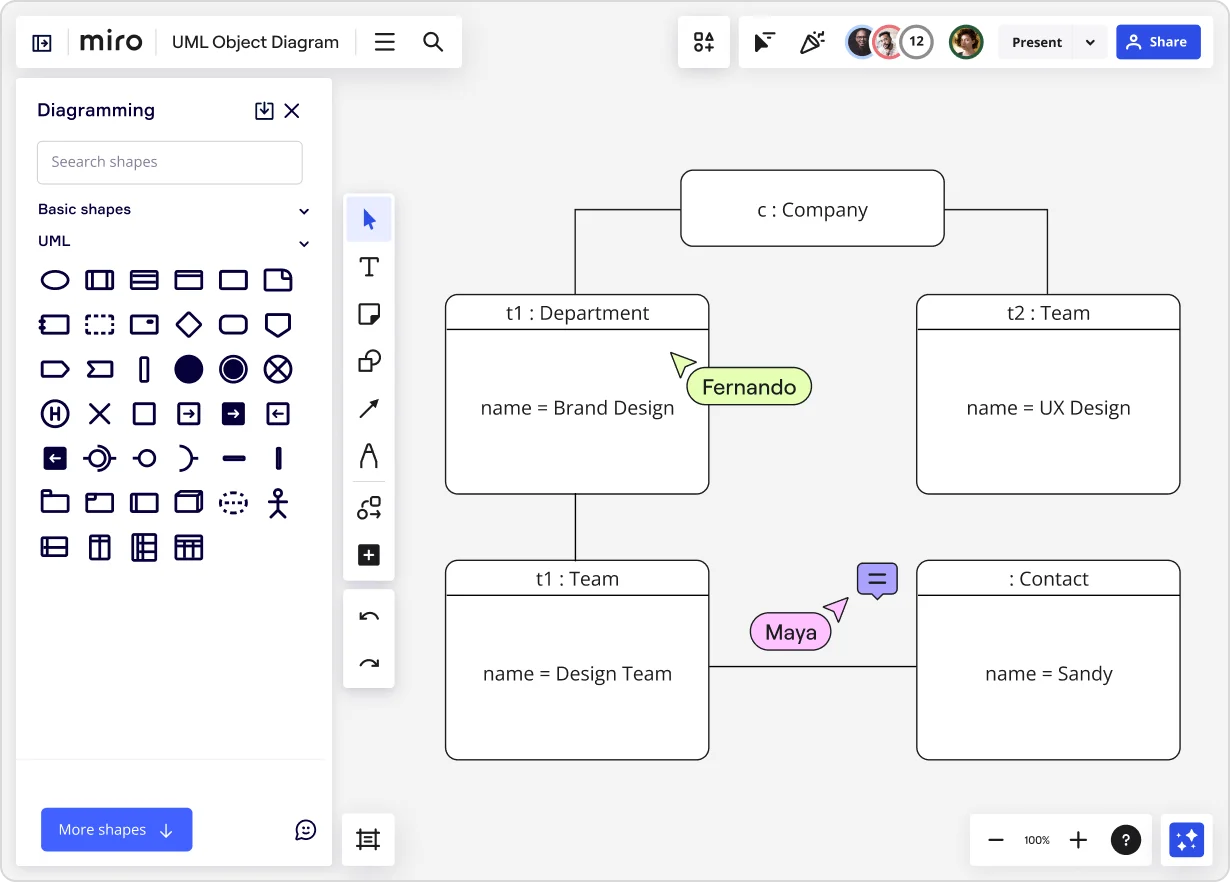
An object diagram in the context of Unified Modeling Language (UML) is a powerful tool used to visually represent the real-world instances of classes and interfaces defined in a system at a particular point in time. It is essentially a snapshot of the dynamic view of a system, capturing how objects are interconnected and interact with each other.
By illustrating objects and their relationships, these diagrams provide a dynamic view of the system, showcasing how various components interact at runtime. This makes them invaluable for both designing new systems and understanding existing ones.
Key components of UML object diagrams
A deep understanding of object diagrams is crucial for effective software design:
Objects and their representation
In an object diagram, each object is represented as a named rectangle, encapsulating the instance's state through attributes. These attributes are not just variables; they are the actual values relevant at the moment the system is observed. This level of detail aids in understanding the specific state and behavior of system components.
Relationships between objects
The relationships in object diagrams are more than mere lines connecting objects; they represent real-time interactions and dependencies. Understanding these relationships is key to grasping the dynamic nature of the system.
Association
Associations in object diagrams are not static; they represent potential pathways through which objects communicate and exchange data, influencing the flow and functionality of the system.
Dependency
Dependencies are critical as they highlight how the modification of one object's state could propagate changes throughout the system, affecting other objects and their behaviors.
Generalization
Generalization relationships in object diagrams help in visualizing the inheritance hierarchy, showing which objects are specializations of others, and thus sharing attributes and methods.
Attributes and methods
The attributes and methods in an object diagram do more than define properties and functionalities; they encapsulate the operational state and potential actions of the object, providing insights into the system's capabilities and limitations.
Understanding multiplicity
Multiplicity is not just about the number of instances; it defines the scope of relationships, indicating potential constraints and freedoms in the system architecture, crucial for scalability and robustness.
How to create a UML object diagram
Drawing an effective object diagram requires careful consideration and attention to detail at each step:
Step 1: Identify relevant objects and their states
Start by examining the system or process you're diagramming. Identify key objects that play a role in the system. Objects can be anything from system components, users, or data elements. Determine the state of each object. This includes the values of attributes at a given point in time. For instance, if the object is a user account, its state could include details like account status, balance, and recent activity.
Step 2: Define relationships between objects
Once objects are identified, discern how they interact with each other. Map out relationships like associations (where two objects are linked), dependencies (where a change in one object affects another), and inheritances (indicating hierarchies among objects). This step is critical as it lays the groundwork for understanding the system’s functionality and constraints.
Step 3: Assign attributes and methods to objects
For each object, list its attributes (characteristics or properties) and methods (actions or functions the object can perform). This helps in understanding not only what the system components are but also what they can do and what information they hold.
Step 4: Represent multiplicity
Determine the multiplicity for each relationship. Multiplicity indicates the number of instances in one class that can be associated with instances in another class. This helps in understanding the scale of interactions and dependencies among objects in the system.
Step 5: Draw the diagram
Utilize a UML tool or software to draw the diagram. Start by placing objects as rectangles labeled with their names and classes. Draw lines to represent relationships, using arrows and labels to indicate the type and direction of each relationship.
Ensure the layout is clear and uncluttered, with enough space to easily discern each element and its connections.
Step 6: Review and refine
After the initial draft, review the diagram for accuracy and completeness. Check if all relevant objects and their relationships are represented correctly. Ensure that the diagram is understandable and effectively communicates the structure and dynamics of the system.
Step 7: Iterate as necessary
Object diagrams often need to be updated as the system evolves. Regularly revisit and revise the diagram to reflect any changes in the system.
Best practices for effective diagrams
A well-crafted object diagram balances detail with clarity. It should be comprehensive enough to provide a full picture of the system’s dynamics, yet straightforward enough to be immediately understandable to stakeholders with varying levels of technical knowledge.
Common pitfalls to avoid in diagramming
A common mistake is either oversimplifying the diagram, which omits crucial details, or overcomplicating it, which obscures understanding. Another pitfall is inconsistency in representation, leading to confusion and misinterpretation.
Object diagrams vs. other UML diagrams
Object diagrams offer a unique perspective compared to other UML diagrams:
- They provide a real-time snapshot, unlike class diagrams that depict a more static view of the system structure.
- When used alongside sequence diagrams, they offer a more comprehensive view of object interactions over time.
- In comparison to use case diagrams, object diagrams offer a more granular, technical view of the system’s functioning.
Advanced topics in UML object diagrams
Incorporating design patterns in object diagrams
Integrating design patterns into object diagrams is a sophisticated practice. It not only enhances the design structure but also ensures that the system adheres to proven solutions to common problems, increasing efficiency and reliability.
Extending object diagrams with stereotypes and constraints
Utilizing stereotypes and constraints turns a generic object diagram into a tailored, specific blueprint for the system, accommodating unique requirements and scenarios.
Tools for drawing UML object diagrams
Choosing the right tool for creating an object diagram can significantly affect the efficiency and accuracy of the process. Consideration should be given to features like real-time collaboration, ease of integration with other development tools, and support for exporting diagrams in various formats.
Miro’s easy-to-use UML diagram tool and extensive shape pack with both real-time and asynchronous collaboration features make it the perfect tool for drawing UML diagrams.
Final thoughts
UML object diagrams provide more than a static representation; they offer a vivid snapshot of a system's operational state at a particular moment. These diagrams are indispensable for developers, system analysts, and stakeholders, bridging the gap between abstract design and tangible functionality.
They not only aid in visualizing the architecture and behavior of a system but also play a vital role in communication, ensuring that all team members have a common understanding of the system's dynamics. As technology continues to evolve and systems become increasingly complex, the role of UML object diagrams in effective software design and analysis is more important than ever.
Author: Miro Team
Last update: October 10, 2025