Table of contents
Table of contents
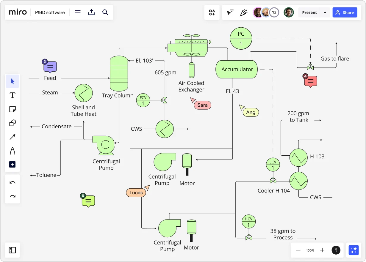
Piping and Instrumentation Diagrams
Summary
In this guide, you will learn:
- What a P&ID is and its role in illustrating process systems
- How P&IDs are essential for designing, operating, and maintaining industrial processes
- Common symbols and notations used in P&IDs
- The difference between P&IDs and other process diagrams like PFDs
- How P&IDs help in troubleshooting, safety, and regulatory compliance
- Best practices for reading, creating, and updating P&IDs
Collaborative AI Workflows
Join thousands of teams using Miro to build the right thing, faster.
What is a P&ID?
A Piping and Instrumentation Diagram (P&ID) is a comprehensive schematic that illustrates the functional relationship of piping, instrumentation, and system equipment components within a process plant. It serves as a vital tool in the process industry, forming the backbone of the design phase and providing a detailed layout of the plant's process.
P&IDs provide engineers and operators with a clear and detailed view of the plant's processes. This visibility is crucial for the following reasons:
Design and Planning: During the design phase, P&IDs are used to lay out the necessary components and systems for the plant. This includes specifying pipe sizes, lengths, and the type of instrumentation required to control the process.
Operation: For day-to-day operations, P&IDs offer guidance on the operational aspects of the plant. They help in understanding the process flow, control loops, and the interconnectivity of different systems.
Maintenance and Safety: P&IDs are also key in maintaining the plant. They help identify and locate equipment for maintenance and troubleshooting. Moreover, they are essential for safety analysis, as they show the location of safety valves, relief systems, and other safety equipment.
Compliance and Documentation: They ensure compliance with industry standards and serve as a historical record of the plant's design and modifications over time.
Overall, creating detailed P&IDs helps to ensure efficient, safe, and compliant industrial operations. They act as a blueprint that stakeholders refer to throughout the plant’s operational lifetime.
P&ID symbols and their meaning
Piping and instrumentation diagrams are comprised of symbols and abbreviations that represent the different components of a process system. Understanding these elements is key to interpreting and using P&IDs effectively.
Common P&ID symbols include:
Lines
Solid lines represent pipes, with their size and material indicated by accompanying letters and numbers. Dashed lines often indicate connections to existing systems or future installations.
Valves
Valves are represented by various symbols depending on their type, such as gate, globe, check, and butterfly valves. These symbols can also include details on how the valve operates, like manual or automatic.
Pumps
Pumps are shown as circles with triangles pointing in the direction of flow. Different types of pumps like centrifugal, positive displacement, or diaphragm pumps have specific symbols.
Instruments
Instruments are depicted by a combination of letters and numbers that specify their type and function, such as transmitters, controllers, and indicators. These are usually tagged with a unique identifier.
Vessels
Tanks, reactors, columns, and drums are shown with shapes that resemble their physical appearance. Additional details may indicate internal components like agitators or heating coils.
Heat exchangers
These are depicted with a basic symbol modified to indicate the type, such as shell-and-tube or plate heat exchangers.
Miscellaneous
Other equipment such as filters, fans, and motors have their unique symbols. Safety devices like pressure relief valves and rupture disks are also represented with standardized icons.
On a P&ID, these elements are arranged to show how they are interconnected within the process system. The lines connect the equipment to illustrate the flow path of the process fluid. Valves are placed along these lines to show where and how the flow can be controlled. Pumps indicate the points of pressure changes and movement.
Instruments are often linked to the equipment they control or monitor with dashed lines. This denotes the relationship between the physical equipment and the control system. The interaction of these elements on the diagram reflects the real-world flow of materials, energy, and signals throughout the plant.
Understanding how these elements interact on a P&ID allows for a comprehensive overview of the process, which is crucial for design, operation, and maintenance of the plant. It ensures that all stakeholders have a common understanding of how the plant operates, which is essential for efficiency and safety.
Reading a P&ID
Interpreting a piping and instrumentation diagram requires a systematic approach to understand the flow direction, operating conditions, and control loops within a process plant. Here are some tips to effectively read a P&ID:
Identifying the flow direction
Flow Arrows: Look for arrows on the lines which indicate the direction in which the process fluid is intended to move through the system.
Equipment Orientation: Recognize the orientation of pumps, compressors, and other flow-driving equipment which typically indicates the flow direction from the inlet to the outlet.
Sequence of Operations: Analyze the sequence of operations by following the lines from one piece of equipment to the next. This logical progression often reveals the flow path.
Understanding operating conditions
Line Labels: Note the labels on the piping lines, which often include information on the size, material, and the fluid conveyed, which can imply pressure and temperature conditions.
Instrument Tags: Pay attention to instrument tags that provide details on the measurement and control points, which can give insights into the operating parameters like pressure, temperature, and flow rates.
Process Annotations: Look for annotations and notes that may specify operating conditions such as pressure ratings, temperatures, or flow quantities.
Recognizing control loops
Control Symbols: Identify the symbols for controllers, transmitters, and control valves. They are usually connected by dashed lines, indicating their relationship in a control loop.
Loop Identifiers: Each control loop should have a unique identifier that helps in tracing the loop throughout the P&ID.
Functional Relationships: Understand the functional relationship between different instruments in a loop. For example, a temperature sensor might be connected to a temperature controller, which in turn operates a control valve to regulate the temperature.
By combining these tips, one can navigate a P&ID with an informed perspective. It's important to start at the beginning of a process and trace through each step, paying close attention to the details and annotations provided. With practice, reading a P&ID becomes an insightful experience that reveals much about the process it represents.
Applications of P&IDs
P&IDs are applied across various stages of a process plant's lifecycle. They are not only essential during the engineering and design phases but also throughout the operation, maintenance, and modification of a plant. Below is a real-world example of how P&IDs can be applied in an industrial setting.
Real-world example: Chemical manufacturing plant
Consider a chemical manufacturing plant that produces a range of products, including plastics, resins, and synthetic fibers. In such a facility, P&IDs serve multiple critical functions:
Design and Construction: Initially, P&IDs are used to design the layout of the plant, which includes the placement of pipes, reactors, distillation columns, and storage tanks. The diagrams help in determining the most efficient pathways for material transfer and the best placement of equipment for optimal process flow.
Operation: Once the plant is operational, P&IDs become an essential reference for the plant operators. For example, if a particular resin must be heated to a specific temperature before being transferred to a storage tank, operators will refer to the P&ID to understand which valves to open and which instruments monitor the temperature and flow rate.
Safety Procedures: P&IDs are critical for safety management. If there's an emergency like a pressure build-up in a reactor, the P&ID will guide the emergency response team to quickly locate the safety valves and pressure indicators to avert a potential hazard.
Troubleshooting and Maintenance: During routine maintenance or when troubleshooting issues, technicians refer to P&IDs to locate the relevant valves, switches, and instruments. If a pump needs to be replaced, the P&ID will show its exact location and the shut-off valves that need to be closed before starting the work.
Upgrades and Expansion: When the plant needs to be upgraded or expanded, P&IDs are updated to reflect the integration of new equipment or piping systems. This ensures that any modifications are documented and understood by all stakeholders.
Through this example, it is evident that P&IDs are an indispensable tool, providing the necessary information to ensure that the plant operates smoothly, safely, and efficiently. Their application is a testament to their value in industrial processes across the globe.
Author: Miro Team
Last update: October 9, 2025