Table of contents
Table of contents
Process and Instrumentation Diagrams Symbols
Summary
In this guide, you will learn:
- Definition and purpose of P\&ID symbols for process systems
- Common instrument symbols like temperature sensors and control valves
- Various valve symbols, including basic and complex types
- Importance of standardization and clarity in P\&ID symbols
- Best practices for effective P\&ID diagram use
- Critical role of mastering P\&ID symbols for process engineers
Collaborative AI Workflows
Join thousands of teams using Miro to build the right thing, faster.
Understanding the basics of P&ID symbols
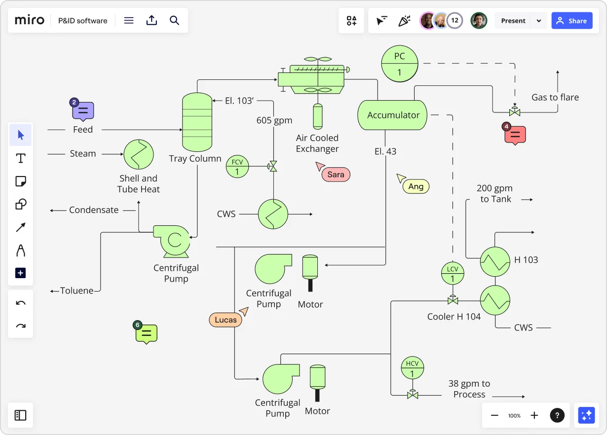
In the intricate world of process engineering, the cornerstone of communication lies within the humble yet profoundly important Process and Instrumentation Diagrams (P&IDs). These blueprints are the language spoken by engineers, technicians, and operators in various industries, providing a comprehensive understanding of processes, instruments, and equipment.
P&ID symbols serve as the visual vocabulary of process engineering. They represent various components and interactions within a system, covering everything from equipment to valves, piping, and instrumentation.
Let's delve into the key categories of P&ID symbols:
Equipment Symbols
Equipment symbols encompass a wide array of machinery. Here you have the main equipment P&ID symbols:
- Pump: Represented by a circle with a triangle inside indicating the direction of flow.
- Compressor: Depicted by a circle with a horizontal line and arrow, symbolizing compression.
- Tank: Illustrated as a rectangle or square with multiple lines for inlet and outlet connections, denoting storage.
Piping Symbols
The representation of piping involves various line types, each carrying its own significance. Some of the piping P&ID symbols:
- Main Process Flow Line: Displayed as a solid line indicating the primary flow of the process.
- Auxiliary or Secondary Flow Line: Represented by a dashed line, indicating secondary systems.
- Different Line Sizes and Patterns: Signify the nature of the flow, whether liquid, gas, or other materials.
Instrument Symbols
Instruments, such as sensors, transmitters, and controllers, have their unique symbols. The instrument P&ID symbols can be:
- Temperature Sensor: Depicted as a circle with a dot inside, indicating temperature measurement at a specific point in the system.
- Control Valve: Represented as a square containing an arrow or line, signifying control of flow or pressure.
Valve Symbols
Valve symbols, crucial for process control, come in various forms. Some examples of valve P&ID symbols are:
- Basic Valve: Displayed as a line with an arrow indicating the direction of flow.
- Complex Valves (e.g., Globe Valve): Depicted with a round shape, a stem, and an arrow indicating control and direction.
Reading P&ID Symbols
Interpreting a P&ID involves understanding the flow of processes. For instance, observing a pump symbol connected to a tank symbol signifies the transfer of material from the tank by the pump.
Moreover, the direction of the flow, whether indicated by arrows or symbols themselves, provides insights into the movement of liquids, gases, or solids within the system.
To gain a comprehensive understanding, it's crucial to pay attention to the consistency and adherence to standards in the use of symbols. The standardization of symbols ensures that professionals worldwide can interpret diagrams accurately, regardless of geographical or industry-specific nuances.
Challenges and best practices
Understanding which P&ID symbols to use is critical to utilizing these types of diagrams effectively. Misinterpretations due to non-standard symbols or variations can lead to errors in operations or engineering.
To combat this, adhering to best practices—such as ensuring clarity, consistency, and utilizing updated software tools—remains imperative.
In conclusion, mastering the language of P&ID symbols is crucial for professionals in the process engineering domain. The ability to interpret and create accurate diagrams not only ensures efficient communication but also plays a pivotal role in the safe and effective operation of industrial processes.
Author: Miro Team
Last update: October 7, 2025