UML collaboration diagrams: a guide
Summary
In this guide, you will learn:
- What a UML collaboration diagram is and its role
- Key elements of collaboration diagrams: objects, actors, links, messages
- How collaboration diagrams show relationships and communication
- Step-by-step process to create a collaboration diagram
- Differences and connections with other UML interaction diagrams
- Scenarios and benefits of using collaboration diagrams
Collaborative AI Workflows
Join thousands of teams using Miro to build the right thing, faster.
In software development, understanding Unified Modeling Language (UML) is essential, and the collaboration diagram is a standout feature within this toolkit. It's an indispensable tool for mapping out complex system interactions, offering clarity and insight into the intricate workings of object relationships.
What is a collaboration diagram?
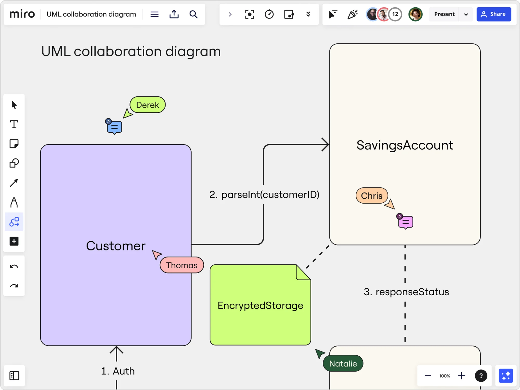
A collaboration diagram is a fundamental aspect of UML, providing a comprehensive visual representation of how objects in a system interact and relate to one another. It's more than just a static image; it's a dynamic map that illustrates the complex web of communications within a system, highlighting how each component collaboratively contributes to the overarching functionality.
Elements of UML collaboration diagrams
Collaboration diagrams, integral to UML, consist of various elements that work together to represent the intricate interactions within a system. Understanding these elements is key to both creating and interpreting these diagrams effectively.
Objects
Objects are the primary components of a collaboration diagram. They can represent entities, classes, or components within the system being modeled. Each object is typically depicted as a rectangle with the object's name inside.

Links
Links denote the relationship or connection between two objects. They are represented by lines connecting the objects. These links indicate that there is some form of communication or interaction between the connected objects.

Messages
One of the most critical elements, messages, are the interactions that occur between objects. They are represented as labeled arrows pointing from the sender object to the receiver object. The label usually describes the nature of the communication or the action that is being invoked.

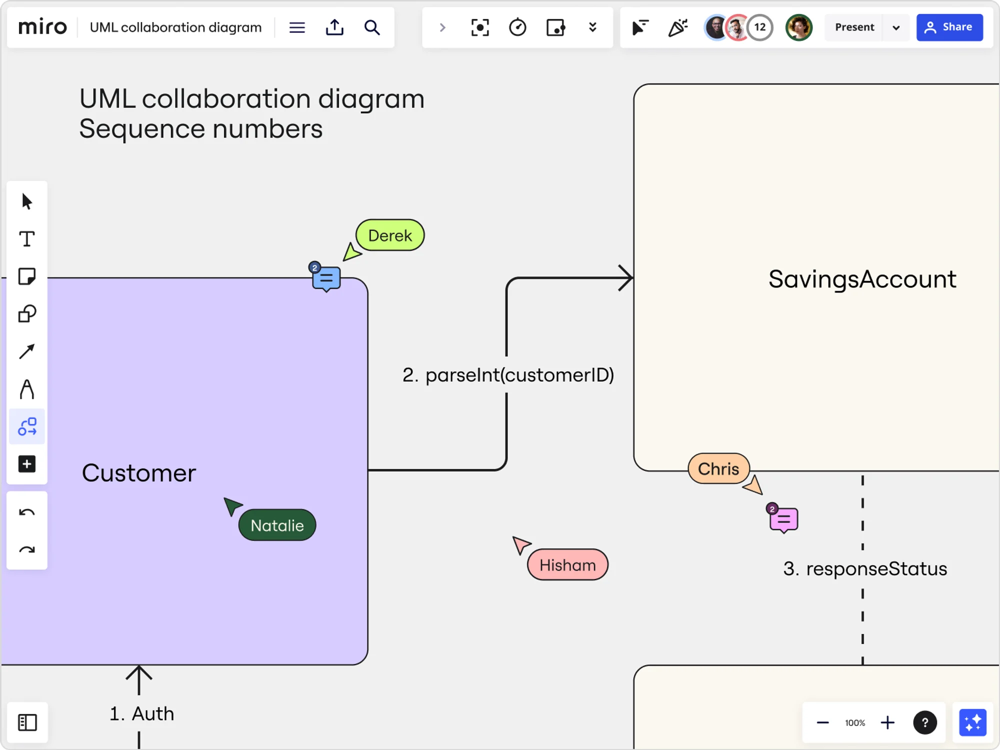
Sequence numbers
Sequence numbers are numerical or alphabetical markers that indicate the order of message flow in the diagram. They play a crucial role in understanding the sequence of interactions and help in tracing the workflow within the system.
Activation bars
These bars, often represented as thin rectangles on an object, show the duration an object is active during an interaction. They help in visualizing the time frame within which an object is participating in the communication process.

Conditions and loops
For more complex interactions, conditions (like if-else statements) and loops (like for and while loops) can be incorporated. These are usually annotated alongside the messages or links and provide a deeper insight into the decision-making processes within the system.

Notes and comments
To add clarity or additional information, notes, and comments can be attached to any of the elements in the diagram. They are usually depicted as a box with a dashed line connecting to the related element.

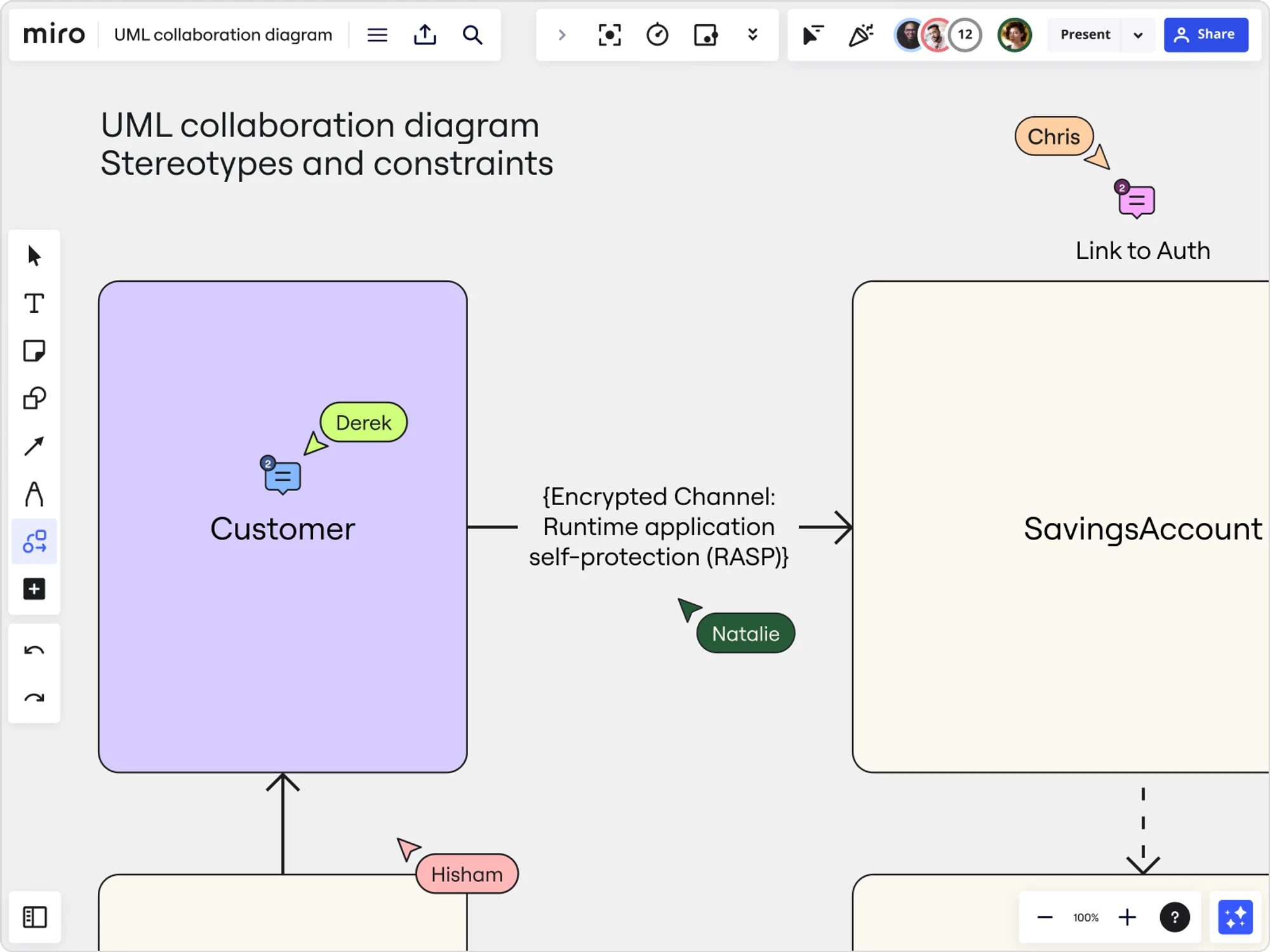
Stereotypes and constraints
In more advanced diagrams, stereotypes (which provide additional semantic meaning) and constraints (which specify limits or conditions on system elements) can be included. These are typically enclosed in curly braces and placed near the relevant diagram element.
Collaboration diagrams vs. sequence diagrams
Collaboration and sequence diagrams are often mentioned together, as they both illustrate interactions within a system. However, the collaboration diagram offers a unique perspective by focusing more on the relationship and interplay between objects, rather than the chronological sequence of events.
This makes it particularly useful in scenarios where the understanding of object relationships is more crucial than the timing of interactions.
How to create a UML collaboration diagram
Creating an effective collaboration diagram involves several key steps, each important for ensuring a clear and comprehensive representation of your system's interactions. Here's a detailed, step-by-step approach:
1. Identify the scope
Start by defining the boundaries of the process or system you want to represent. What is the start point, and where does it end? This step sets the stage for what will be included in your diagram.
2. List the objects
Identify all the objects (or classes) that will be part of the diagram. Objects can be anything from system components and actors involved in the process to data entities. Be thorough but relevant.
3. Determine relationships between objects
Once you have a list of objects, define how they interact with each other. Are they sending messages? Do they collaborate on specific tasks? This step is crucial for understanding the dynamics of your system.
4. Sketch a rough diagram
Begin with a rough sketch of your diagram. Place the objects and draw lines to indicate interactions. Use standard UML symbols to represent different types of interactions and relationships.
5. Assign sequence numbers
Sequence numbers are vital in a collaboration diagram as they indicate the order of interactions. Assign sequence numbers to each interaction, making sure they reflect the actual flow of the process.
6. Add details to interactions
For each interaction, add necessary details like the condition under which the interaction happens, the message passed, and any return action. This information provides depth to your diagram.
7. Validate the flow of interactions
Review the diagram to ensure that the sequence of interactions makes sense and accurately represents the process. This step might require consultation with team members or stakeholders for accuracy.
8. Refine and finalize the diagram
Based on feedback and additional insights, refine your diagram. Adjust the layout for clarity and ensure that all elements are correctly labeled and sequenced.
9. Review and share
Finally, review your diagram for any last-minute adjustments. Once finalized, share it with relevant stakeholders. This could include team members, project managers, or clients, depending on the purpose of the diagram.
Advanced techniques in collaboration diagrams
Enhancing collaboration diagrams with advanced techniques is key for effectively depicting complex interactions. These advanced elements add depth, making the diagrams more insightful:
Conditional messaging
Incorporate conditional expressions to represent interactions dependent on specific conditions, which are crucial for modeling complex decision-making.
Looping and iterations
Use loop conditions on messages for interactions that repeat, essential for processes involving repeated actions.
Parallel and concurrent interactions
Indicate simultaneous processes with parallel interactions, showcasing the ability of systems to handle multiple tasks at once.
Time constraints and delays
Annotate interactions with time expressions to highlight critical timing aspects, enhancing the temporal accuracy of the diagram.
Refinement of objects and interactions
Break down complex objects and interactions into simpler components for a more detailed view of system operations.
Integration with other UML diagrams
Combine collaboration diagrams with other UML diagrams like Sequence and State Diagrams for a comprehensive system perspective.
Utilizing advanced UML features
Leverage UML's advanced features like signal sending and exception handling to model sophisticated system behaviors.
These techniques transform collaboration diagrams into more dynamic tools, capable of representing the intricate workings of complex systems in a nuanced and detailed manner.
Tools for collaboration diagrams
Modern UML tools have revolutionized the process of creating collaboration diagrams. With features like intuitive drag-and-drop interfaces and real-time collaboration, these tools have become essential in today's software development landscape.
Miro’s UML diagram tool, for example, is easy to use and with an extensive shapes library for whatever your needs are. On top of that, it's packed with powerful real-time and async collaboration features to bring your team together online seamlessly.
Final thoughts
UML collaboration diagrams are a key tool in the arsenal of any software developer or system analyst. They provide a clear, detailed view of system interactions, making complex relationships understandable and manageable. For both novices and experts in the field, mastering these diagrams is a step toward more efficient and effective project development and system analysis.
One of the primary challenges in creating collaboration diagrams is maintaining a balance between comprehensive detail and overall clarity. To ensure that the diagram remains relevant and accurately reflects the system it represents, regular updates and reviews are necessary. This ongoing maintenance is crucial for keeping the diagram aligned with any changes or evolutions within the system.
Author: Miro Team
Last update: October 10, 2025